Allen Bradley 2711P series PanelView Plus human-machine interface terminal
Product positioning and model system
This document is the official manual for the 2711P PanelView Plus series HMI terminal, covering 6 sizes:
400 (3.5 “), 600 (5.5”)
700 (6.5 “), 1000 (10.4”), 1250 (12.1 “), 1500 (15”)
It is divided into standard version and CE version. The CE version comes pre installed with Windows CE.net and supports custom programs and desktop operations.
Core software: FactoryTalk View ME Station, running * * MER * * project files.
Model coding rules
Meaning of encoding segments
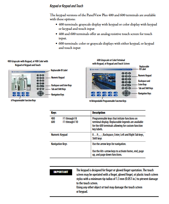
K button
T Touch
B button+touch
Size 4/6/7/10/12/15
C Color
M grayscale
A/D AC/DC power supply
1/2/3 memory configuration
6/7 CE version logic module
Installation specifications
1. Environmental requirements
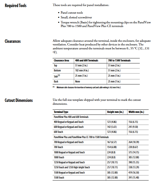
Working temperature: 0~55 ℃
Explosion proof rating: Class I Div 2, Zone 2
Pollution level: 2, overvoltage category II
Cooling distance: Up and down * * ≥ 51mm * *, left and right * * ≥ 25mm**
2. Hole size (core)
Model width x height (mm)
400 156 × 123
600 241 × 142
700 264 × 167
1000 375 × 224
1250 390 × 257
1500 419 × 305
3. Fixed method
400/600: Install the buckle
700~1500: Installation clip+torque tightening (0.9~1.1N · m)
Sealing: Comes with waterproof adhesive tape as standard, does not use sealant
Power wiring
1. Power supply specifications
Type Voltage Range Maximum Power Consumption
DC 18~32V 70W
AC 85~264V 160VA
2. Grounding requirements
DC model: Functional grounding must be connected, wire diameter 14~10AWG
AC model: protective grounding+functional grounding dual grounding
Grounding resistance: ≤ 100 Ω
3. Wiring specifications
Wire diameter: 22~14AWG
Torque: 0.45~0.56N · m
Do not plug or unplug terminals with power on
Configuration mode (core operation)
The configuration mode is the entry point for HMI core settings and supports the following functions:
Load/Run Application: Load * * from internal/external CF card MER**
Terminal settings
Display: Brightness 0-100%, screensaver 5-30 minutes
Input: Touch calibration, double-click sensitivity, key anti misoperation
Time: Date, Time Zone, Summer Time
Region: Language, Number Separators, Date Format
Communication Configuration
Ethernet: DHCP/Static IP
Serial port: DF1, DH-485, baud rate 9600~115200
Bus: DH+, ControlNet, DeviceNet
boot options
Enter configuration mode
Automatically run the current application
Startup deletion log
Windows CE.net system (CE version exclusive)
The CE version provides a complete Windows desktop environment, pre installed with:
Internet Explorer, WordPad, PDF Reader
Remote desktop, FTP server ActiveSync
File Explorer, Control Panel
Control panel functions
Network: Ethernet IP, dial-up
Display: Backlight, screensaver, cursor
Input: touch, buttons, mouse
System: Memory allocation, device names, diagnostics
Security: Password, certificate
Hardware component replacement (700~1500 supported)
Replaceable components
Logic modules (RP1/RP2/RP3/RP6/RP7)
Display modules (RDK7/RDT10/RDB12, etc.)
Communication module (RN3/RN6/RN15C/RN15S)
Battery (2711P-RY2032)
Backlight, border, button nameplate
Key points for replacement
Must be powered off+anti-static wristband
Screw torque: 0.58N · m
Components must match the same series
Communication connection
Support protocols and ports
Communication method port speed
Ethernet RJ45 10/100M
RS232 DB9 115200bps
DH‑485 RJ45 19200bps
DH+coaxial 57.6K~230K
ControlNet BNC 5M
DeviceNet 5-core 125K~500K
Wiring restrictions
Maximum serial port length: 15m
Ethernet maximum length: 100m
Bus cable: shielded twisted pair/coaxial
Firmware and system upgrade
Three upgrade methods
CF card upgrade: Create upgrade card → Insert → Automatic upgrade
Ethernet upgrade: FUW tool → IP direct connection → online upgrade
ActiveSync: CE version upgrades through serial/network port synchronization
Upgrade points
Backup the application and record the IP address before upgrading
Prohibit upgrading and power interruption
Re calibrate touch after upgrading
Troubleshooting
Common startup error codes
Error code meaning handling
1 RAM detection failed, restart/replace memory/logic module
24 CRC check failed and firmware was flashed again
30 watchdog error replacement logic module
31 Button Adhesion Check Button/Replace Display
32 battery failure, battery replacement
Common problem handling
Unable to connect to the internet: Check IP, network cable, and switch
Inaccurate touch: recalibrate touch
Application not running: Check MER version, startup settings
Black screen: Check power, backlight, brightness
Maintenance and Disposal
Cleaning: Power off → Soft cloth+neutral cleaner → Air dry
Backlight: Contains mercury, professionally recycled
Battery: Lithium manganese battery, incineration is prohibited
Cycle: Regular inspection of sealing, grounding, and wiring
Key questions and answers
Question 1: How to set PanelView Plus to automatically run MES projects upon startup? How to recover from configuration errors?
answer:
Enter Configuration Mode → Terminal Settings → Startup Options
Select Run Current Application
Set Replace RSLinx Communications and Delete Log Files
Save and restart to automatically run
Recovery method:
Press and hold the white box/F1 key during startup to force entry into configuration mode
CE version can enter Safe Mode (Default+Reset) to disable boot up
Question 2: How to troubleshoot the Ethernet communication failure of 711P terminal (Winsock 10065 error) according to the steps?
answer:
Physical inspection: The green light on the network port is always on, and the yellow light is flashing
Confirm IP: Same network segment, no 169.254. x.x automatic address
Check for conflicts: No duplicate IP/device names
Test link: Ping command for connectivity
Driver inspection: RSLinx Enterprise driver is normal
Reset: Reconfigure IP or restart terminal
Question 3: What hardware can be replaced on site for 700~1500 models with touch failure/display abnormalities? What are the mandatory safety requirements for replacement?
answer:
Can be replaced on-site: display module, backlight, logic module, battery, communication module, border
Mandatory requirement:
It must be completely powered off and wait for the capacitor to discharge
Wear an anti-static wristband to prevent damage from static electricity
Tighten screws to standard torque
Replacement components must be of the same model and series
Touch calibration and power on self-test after replacement