NI cFP-2200/2210/2220 Compact FieldPoint Intelligent Real time Controller
Product positioning and applicable models
This document is the operation and specification manual for NI cFP-2200/2210/2220 intelligent real-time controller, aimed at Compact FieldPoint distributed I/O system, used for real-time control, data acquisition, remote I/O in industrial sites, supporting use in harsh environments and explosion-proof areas.
Safety regulations and environmental requirements
Explosion-proof certification
Class I, Division 2, Groups A/B/C/D, T4
Zone 2:Ex nL IIC T4, IP54 protective chassis required
Safe wiring
The PE grounding terminal of the backboard must be connected to the system safety ground, using 14AWG cable with wire ears
Power supply and module can only be plugged in and out after power failure
working environment
Temperature: -40~70 ℃
Humidity: 10%~90% RH (no condensation)
Protection level: IP20
Hardware Structure and Interface
1. Differences in core models
Model Memory Network Port Serial Port USB CF Card DIO
cFP-2200 128MB NV+128MB DRAM 1×RJ45 1×RS232 – – –
cFP-2210 128MB NV+256MB DRAM 1×RJ45 2×RS232 – – –
CFP-2220 256MB NV+256MB DRAM 2 x RJ45 3 x RS232+1 x RS485 1 x USB support 2 in 2 out
2. Key interfaces
Power supply: Dual input V1/V2, 11~30VDC, automatically selecting high voltage power supply
Ethernet: 10/100Mbps adaptive, maximum line length 100m
Serial port: RS232 up to 115200bps; RS485 with 100Vrms isolation
Storage: cFP-2220 supports CF cards (up to 512MB) and USB flash drives
DIO: 2 in 2 out (5V logic, non isolated, only for local operation)
Installation and fixing steps
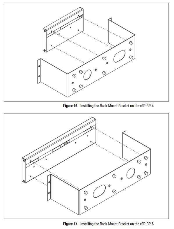
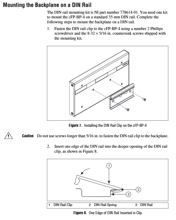
Backboard installation (cFP-BP-4/BP-8)
Method: 35mm DIN rail, panel, 19 inch rack
Spacing: Reserve ventilation around * * ≥ 51mm, controller up and down 51mm/38mm**
Controller installation
After power off, align the backplane connector and tighten the captive screw with a torque of 1.1N · m
I/O modules and wiring terminals
Install the modules and cFP-CB-x terminal block in sequence, and perform power-off operation
grounding
Backboard PE terminal connected to protective ground, 14AWG cable
Power and network wiring
1. Power wiring
Dual power supply: V1/V2, common ground, internal automatic selection of higher voltage
Magnetic ring must be installed: the power cord should be wound twice, with a distance of 5-8cm from the connector
Power consumption: 6.1W+power consumption of each I/O module
2. Network connection
Ethernet cable: CAT5 and above, both direct and crossover cables are acceptable
Configuration: Use MAX software to allocate IP addresses within the same network segment, and dual network ports (2220) can form a private network
Serial port and peripheral connection
RS232: DB9 and modular interface for device communication
RS485 (2220): 4-wire system, with 120 Ω terminal resistors connected at both ends
USB (2220): Only supports specified USB drives, mapped to U:, not hot swappable in hazardous areas
CF card (2220): Power off plug and unplug, mapped to D:
DIP switch function (6-digit)
IP RESET: ON → Restart and reset IP to 0.0.0.0
SAFE MODE: ON → Safe Mode, does not start the RT engine, used for repairing/formatting
NO APP: ON → Disable automatic VI operation upon startup
CONS-OUT: ON → Serial port printing IP and version (9600, N, 8,1)
USER1/USER2: Custom Features
LED status indication
POWER: Always on=power supply is normal; Green=V1, Amber=V2
Status (abnormal flashing light)
Flash once: Not configured
Flash 2 times: Software error
Flash 3 times: Safe mode
Flash 4 times: Out of memory/Two crashes
Always on: Unrecoverable fault
ABCD: User programmable, green/amber/off three states
Troubleshooting and Recovery
Program loss of control: Restart by dialing NO APP or SAFE MODE, prohibit startup VI
Unable to connect to the internet: IP RESET Reset IP, Reconfigure
System damage: MAX formatted disk in SAFE MODE, reinstalling software
Lamp abnormality: locate the fault by comparing the number of flashing lights
Electrical and Mechanical Specifications
Power supply: 11~30VDC, Class 2 power supply
Shock/vibration: 30g/11ms, 5g/10~500Hz
Wiring specifications
Power supply: 14-30AWG
DIO:16~28AWG
Torque: 0.5~0.6N · m
Weight: 278g
Key questions and answers
Question 1: How does the dual power supply V1/V2 of cFP-22xx work? What are the mandatory requirements for wiring and magnetic rings?
answer:
Working logic: The controller automatically selects the higher voltage power supply path, and the two paths will not supply power simultaneously; The voltage difference can be switched freely within 0.1~0.6V.
Wiring requirements: The two power sources must share the same ground, and the C terminal must be internally connected.
Magnetic Ring Mandatory: Each power supply must be equipped with a magnetic ring, and the cable must be wound 2 times, 2-3 inches away from the power connector, to meet EMC compliance.
Question 2: How to properly network the RS485 port of cFP-2220? Why doesn’t NI recommend a 2-wire system?
answer:
Correct connection method: Using 4-wire full duplex, parallel 120 Ω terminal resistors at both ends, and A/B differential corresponding wiring.
Network capacity: can control up to 24 FP-1001 modules.
Not recommended for 2-wire system: it will generate echo reflection, and the software needs to filter out echoes separately, resulting in poor stability.
Question 3: The controller cannot be searched in MAX. What are the standard recovery procedures?
answer:
Dial IP RESET=ON, press RESET to restart, and if STATUS flashes once, it means the IP has been reset.
Set the computer and controller to the same network segment and search again.
Still ineffective: Restart by dialing SAFE MODE=ON and formatting the disk after entering safe mode.
Reinstall LabVIEW RT 8.5.1+and FieldPoint software, and then restore normal mode.