OMRON NE1A Series Secure Network Controller Operation Manual
Product positioning and safety certification
This document is the operation manual for the NE1A series secure network controller, used for mechanical functional safety distributed control systems.
Coverage model:
No EtherNet/IP: NE1A SCPU01 (- V1), NE1A SCPU02
Equipped with EtherNet/IP: NE1A SCPU01 EIP, NE1A SCPU02 EIP
Core Security Certification:
IEC 61508 SIL3
EN ISO 13849-1 PLe/Safety Category 4
EN 62061、UL 508、Class I Div 2
Hardware specifications and interfaces
1. Comparison of I/O models
Model safety input test output safety output
NE1A – SCPU01 (- V1)/- EIP 16:04:08
NE1A – SCPU02/- EIP 4:08:08
2. Electrical specifications
Power supply: 24VDC (20.4~26.4V)
Working temperature: -10~55 ℃
Protection level: IP20
Installation: 35mm DIN rail, ventilation ≥ 5mm (side), ≥ 50mm (top and bottom)
Wiring: 0.2~2.5mm ², screw torque 0.5N · m
3. Interface and indicator lights
Communication: DeviceNet, USB 1.1, EtherNet/IP (EIP)
Display: 7-segment digital tube (node/error code) MS/NS/LOCK/COMM LED
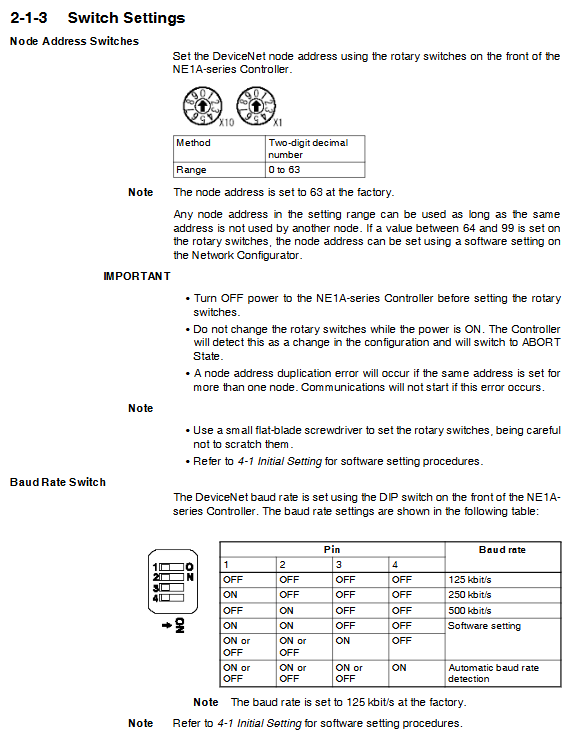
Dialing: Node address (0~63), baud rate (125k/250k/500k)
Communication function (core)
1. DeviceNet Safety
Secure main station: up to 32 connections (Ver1.0+), supporting unicast/multicast
Secure Slave: Up to 4 connections, maximum 16 byte I/O
Standard Slave: Up to 2 connections, supports Poll/COS/Cyclic
Baud rate: 125k/250k/500kbps, supports automatic detection
2. EtherNet/IP (EIP model)
IP settings: BOOTP or static IP (default 192.168.250.1)
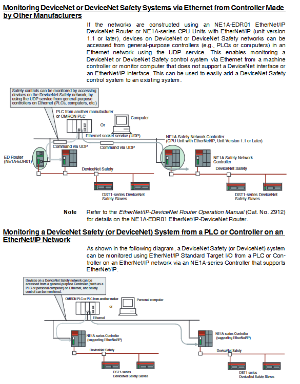
Function: Standard I/O communication, explicit messaging, UDP packets, routing
UDP port: 64000, supports cross network access to DeviceNet devices
3. Remote I/O allocation
Mapped: General state, local I/O state, monitoring data, user tags
Security attribute differentiation: Security data can be used for security circuits; Non secure data is only used for monitoring purposes
Safe I/O Control (Core)
1. Secure input
Channel mode: unused/test pulse input/safe input/standard input
Dual channel mode:
Equivalent dual channel: Only when both channels are turned on simultaneously, is it effective
Complementary dual channel: One NO and One NC cooperation
Diagnosis: Differential time (0-65530ms), incorrect lock (default 1000ms)
2. Test output
Mode: Pulse Test, Standard Output, Shielded Lamp Output
Function: Output diagnostic pulses to detect input circuit short circuits, disconnections, and grounding faults
3. Safe output
Mode: Safe Output/Safe Pulse Test
Diagnosis: overcurrent protection, dual channel linkage, output short circuit detection
Mandatory requirement: Prohibit using test output as safe output
Programming and Function Blocks
1. Programming environment
Software: Network Configurator
Editor: A graphical logic editor that supports direct drag and drop of I/O tags
Capacity: Up to 254 functional blocks for Ver1.0 and above
2. Core functional blocks
ESTOP: Emergency stop button monitoring, supports dual channel
Light Curtain: Safety Light Curtain Monitoring
Safety Gate: Safety Gate monitoring, supporting synchronized time
Two Hand Control: Two Hand Control
Reset/Restart: Manual reset/restart, prevent automatic recovery
Logic: AND, OR, NOT, RS-FF, comparator
Operation mode and fault diagnosis
1. Operation mode
RUN: Normal operation
IDLE: Stop output, can be monitored
CONFIG: Configuration Download
SAFE MODE: System Repair
2. Fault diagnosis
7-segment code display: error code+node number
LED status:
MS green=running; Red=fatal error
NS green=communication is normal; Red=Fault
Yellow LOCK=configuration effective lock
Error History: Record fault type, time, and status
3. Common Error Handling
Error code meaning handling
P4 input power abnormality check V1/G1
P5 output power abnormal inspection V2/G2
Nd DeviceNet disabled (standalone mode) normal
D5/d6/dA Safety communication fault inspection slave station EPI、 line
Maintenance and safety regulations
1. Maintenance function
Contact action counter: Count the number of suction and closing times (0~4294967295)
Accumulated ON time monitoring: Count the duration of power on
Threshold alarm: life warning can be set
2. Mandatory safety taboos
Prohibit using standard I/O, explicit messages, UDP data as security signals
Prohibit overload connection to safety output
It is necessary to use a forced guiding contact relay and directly disconnect the emergency stop
After the power is cut off in the dangerous area, plug and unplug the wiring
Key questions and answers
Question 1: What are the two modes of dual channel safety input for NE1A? What scenarios are they used for? What is the effect of differential time?
answer:
Equivalent dual channel: Both channels are NC normally closed inputs, and simultaneous actions (such as emergency stop buttons and safety switches) must be turned on/off simultaneously to be effective.
Complementary dual channel: one NO and one NC, reverse action, used for safety doors and limit switches.
Differential time: Monitor the interval between changes in two signals, determine faults when timeout occurs, cut off outputs, and prevent switch failure or wiring errors.
Question 2: How many slave stations can NE1A carry as a Safety Master? What are the three recovery strategies after a communication failure?
answer:
Load capacity: Up to 32 secure slave connections for Ver1.0 and above; There are only 16 Pre Ver.
Fault strategy:
Automatic recovery: automatic reconnection after fault elimination
Only stop faulty connections: keep other connections running
Stop all connections: The entire line enters a safe state and needs to be manually reset
Question 3: What is the use of UDP/IP message function with EIP model? What are the communication format and port?
answer:
Purpose: Ethernet devices (PLC/PC) can directly access DeviceNet Safety slave stations through UDP, enabling cross network monitoring without the need for additional gateways.
Specifications:
Port: 64000 (FA00hex)
Command length: Maximum 492 bytes
Response length: maximum 496 bytes
Restrictions: Only Ver1.1 and above – EIP models are supported.