NEC NL8060BC26-17 LCD Module
Product Overview
NL8060BC26-17 is a 10.4-inch industrial grade TFT color LCD module produced by NEC, designed for industrial control display scenarios.
Driving method: a-Si TFT active matrix
Resolution: 800 × 600
Display color: 262144 colors (6 bits x 3)
Backlight: Double Cold Cathode Fluorescent Lamp (CCFL), replaceable lamp holder
Features: Flip scanning direction, wide viewing angle, low reflection, DE data enabled
Core mechanical and appearance parameters
Parameter values
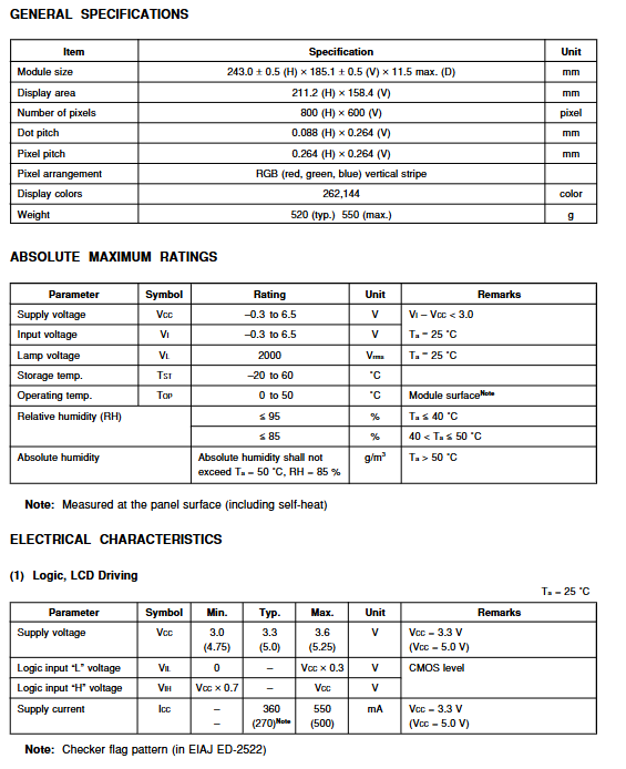
Module size 243.0 (H) × 185.1 (V) × 11.5 (D) mm
Display area 211.2 × 158.4mm
Pixel spacing 0.264 × 0.264mm
Weight 520g (typical)/550g (maximum)
Install screw 4 × M2, torque ≤ 0.294N · m
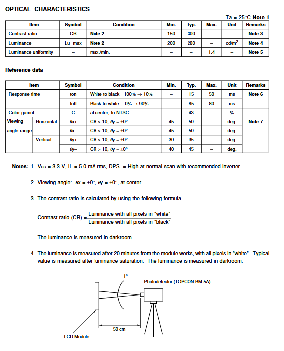
Optical properties (Ta=25 ℃)
Typical parameter values description
Brightness 280cd/m ², lamp current 5mA rms
Contrast ratio of 300:1 all white/all black brightness ratio
Response time 15ms White 100% → Black 10%
Horizontal viewing angle ± 50 ° CR>10:1
Vertical viewing angle of 35 °/45 ° CR>10:1
Color gamut 43% NTSC center point
Electrical characteristics
Logic power supply
Voltage: 3.3V or 5.0V
electric current: 360mA@3.3V ; 270mA@5V
Power consumption: 7.0W (typical, including inverter)
Backlight parameters
Lamp current: 5.0mA rms
Lamp voltage: 510V rms
Starting voltage: 840V rms (25 ℃)
Oscillation frequency: 54kHz
limit parameter
Supply voltage: -0.3~6.5V
Lamp voltage: 2000V rms
Working temperature: 0~50 ℃
Humidity: ≤ 95% (below 40 ℃)
Interface and Pin Definition
Main connector CN1: DF9-41P-1V
Power supply: VCC (39/40 pins) GND
Signal: CLK, HSync, VSync, DE
Data: R0~R5, G0~G5, B0~B5 (6-digit RGB)
Control: MODE, DPS (scanning direction)
Key control foot
MODE=H: Fixed mode; MODE=L/Suspended: DE mode
DPS=VCC: forward scan; DPS=GND/Suspended: Reverse Scan
Backlight connector CN2/CN3
Lamp high voltage: VHIGH (2/3 pins), VLOW (1 pin)
Dimming: BRTC (switch), BRTH/BRTL (voltage/resistance dimming)
Display mode and scanning direction
Two display modes
Fixed mode: Use HSync/VSync for full timing
DE mode: Only controlled by the Data Enable signal
Scan direction switching
Positive direction (DPS=VCC): The 6-point direction is the optimal viewing angle
Reverse (DPS=GND): 12 o’clock direction is the best viewing angle
Input signal timing
Pixel clock: 38.362MHz (typical)
Cycle time: 26.693 μ s
Field period: 16.683ms (approximately 60Hz)
Timing requirements: Establish/maintain strict time matching and ensure uninterrupted signals
Power on timing requirements (mandatory)
First, go to VCC and send the video signal within 35ms
Backlight is turned on within the LCD working range
When the power is cut off, the signal first pulls low/high resistance, and then disconnects VCC
The signal level must be consistent with VCC
Reliability and Precautions
High temperature and high humidity operation: 50 ℃/85% RH, 240 hours
Temperature cycle: 0 ℃ ↔ 55 ℃, 50 times
Vibration: 5-100Hz, 2G
Impact: 55G, 11ms
ESD:±10kV
Taboos: Do not press the panel, do not plug or unplug with electricity, anti-static, anti condensation
Key questions and answers
Question 1: How to switch the scanning direction of the LCD module? What is the optimal viewing angle for different directions?
answer:
Switching scanning direction through DPS pin level:
DPS connected to VCC → forward scanning, optimal viewing angle is in the 6 o’clock direction (bottom)
DPS connected to GND or suspended → reverse scanning, optimal viewing angle is in the 12 o’clock direction (up)
This design can flexibly adapt to the top-down/bottom-up requirements of industrial installation.
Question 2: What are the electrical rules that must be followed for the power supply and signal interface of the module? What are the consequences of violating?
answer:
Must comply with
The power supply supports 3.3V or 5V, and the signal level must be consistent with VCC
Power on sequence: VCC first, signal sent after 35ms; Power outage sequence is reversed
Do not lose CLK/HSync/VSync during operation, otherwise it will damage the screen
The backlight must be turned on and off within the LCD working range
Violation may cause the screen to instantly turn white, burn the driver IC, or result in permanent afterimages.
Question 3: What are the components of the backlight system of this module? What is the recommended inverter model? How to adjust the brightness?
answer:
Backlight composition: dual cold cathode fluorescent tubes+replaceable lamp holders
Recommended inverter: 104PWBR1
Brightness adjustment method:
Switch: BRTC=H on/L off
Two level dimming: BRTHL=H (100%)/L (60%)
Continuous dimming: Connect a 10k potentiometer or 0~2.5V voltage between BRTH-BRTL