Schneider Altivar Machine ATV320 frequency converter
Schneider Electric Altivar Machine ATV320 Inverter Installation Manual (NVE41289.07, June 2023), designed for asynchronous/synchronous motors, covers the power range of 0.18-15kW, and offers four structures: Book/C Compact/IP65/IP66. It specifies safety specifications, mechanical installation, electrical wiring, EMC filtering, control terminals, and maintenance processes, emphasizing 15 minute power outage discharge, STO safe torque shutdown, SCPD short circuit protection, derating curve, cable length limitation, and is compatible with voltage levels of 200-600V. It supports Modbus/CANopen communication and is a compliant operating basis for industrial site installation and commissioning.
Safety regulations (mandatory requirement)
Power outage safety
After power failure, wait for 15 minutes until the DC bus discharges to * *<42Vdc * * before operation.
Grounding requirements
Grounding resistance * * ≤ 1 Ω * *, minimum cross-sectional area of PE wire 10mm ² (copper wire).
safety function
STO (Safe Torque Off): Safe torque off, in compliance with mechanical safety standards.
Leakage current warning
The equipment leakage current * *>3.5mA * * must be reliably grounded.
Personnel Requirements
Only for professional electrical personnel to install, debug, and maintain.
Product Structure and Appearance
ATV320 is divided into four structures:
Structure code, shape type, protection level
B Book Type IP20
C Compact IP20
W waterproof type IP66
WS waterproof with switch type IP65
Installation requirements
environmental conditions
Working temperature: -10 ℃~+60 ℃ (rated below 50 ℃)
Altitude: ≤ 1000m without downgrading, with a 1% downgrading for every 100m increase between 1000-3000m
Pollution level: Level 2 (conventional)/Level 3 (waterproof)
Installation spacing
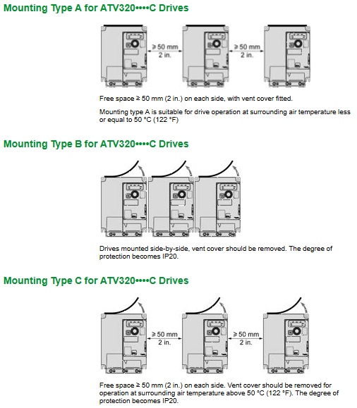
B/C type: Up, down, left, right * * ≥ 50mm**
W/WS type: Up and down * * ≥ 100mm**
Installation direction
Vertical installation, tilted * * ≤± 10 °**
Electrical wiring (core)
1. Power and motor terminals
Terminal function
L1/L2/L3, N three-phase/single-phase power input
U/V/W motor output
PA/+, PC/- DC bus
PB braking resistor
PE protective grounding
2. Control terminals
Digital input: DI1-DI6 (24Vdc, source/drain switchable)
Analog input: AI1/AI2/AI3 (0-10V/0-20mA)
Relay output: R1/R2 (250Vac/30VDC, 5A)
Communication: RJ45 (Modbus/CANopen)
3. Cable requirements
The maximum length of the motor wire is 50m (shielded), and if it exceeds this, an output filter needs to be added
Separate the wiring of power lines and signal lines, with a spacing of ≥ 20cm
Protection and EMC
Short Circuit Protection (SCPD)
IEC circuit breakers/fuses must be configured, with a maximum SCCR of 100kA
EMC filter
Standard built-in filter, IT system needs to disconnect the filter jumper
EMC measures
Shielded cable double ended grounding
Multiple grounding points for cabinets, door panels, and installation plates
Separate wiring for strong and weak electricity
Debugging and Inspection
Before powering on, 6 checks must be performed:
Mechanical installation is firm and the spacing is compliant
The wiring is correct and the terminal torque meets the standard
PE grounding is reliable
Matching of motor and frequency converter parameters
No debris, complete cover plate
STO wiring is correct
Maintenance and scrapping
Regular maintenance (at least once a year)
Clean dust and check for corrosion
Tighten all terminal screws
Check the operation of the fan
Long term storage
Stored for over 12 months, activated capacitor after 1 hour of power on
scrap disposal
Classify and recycle materials, following RoHS/REACH
Key issues
Question 1: Why do I have to wait for 15 minutes to operate the ATV320 frequency converter after it is powered off? How to verify the absence of electricity?
answer:
The DC bus capacitor inside the frequency converter stores high-voltage electrical energy, which will not disappear immediately after power failure; Waiting for 15 minutes can ensure that the capacitor discharges to a safe voltage of * *<42Vdc * *, avoiding the risk of electric shock/arc.
Non electric verification method: Use a multimeter to measure the voltage between * * PA/+and PC/- * *, and confirm that it is less than 42Vdc.
Question 2: What key operations must be performed when using ATV320 in IT power distribution systems? Why?
answer:
The Y capacitor jumper/screw with built-in EMC filter must be disconnected.
Reason: The IT system is a neutral ungrounded system, and the Y capacitor of the filter can cause abnormal ground leakage current, insulation monitoring false alarms, and equipment overvoltage damage. It can only operate safely after disconnection.
Question 3: What are the risks associated with ATV320 motor cables exceeding 50m? How to solve it?
answer:
Risk: If the motor wire is too long, it can cause reflection overvoltage, with a peak value of up to twice the bus voltage, which can break through the motor insulation.
Solution:
Install output reactor/filter
Enable the frequency converter * * motor surge limit (SUL) * * function
Reduce the switching frequency to below 4kHz
Use frequency conversion dedicated motor (IEC 60034-25)