IFM CR2530 SmartController Installation Manual
Product positioning
Product: ifm CR2530 SmartController, a high protection programmable controller for mobile machinery/vehicles
Target audience: Professional electrical technicians
Core application: Distributed control of construction machinery, commercial vehicles, and special vehicles
Safety Notice (Key)
Operation qualification
Only qualified electricians are allowed to install, wire, and power on, following EMC and low voltage instructions.
Electrical safety
The power supply must comply with the SELV safety ultra-low voltage standard
External power must be disconnected before power on operation, and hot plugging of the 55 pin connector is prohibited
Before welding, all joints of the controller must be disconnected
Usage restrictions
Cannot be used for personal safety related functions
It is prohibited to disassemble, modify, or tamper with equipment
environmental safety
The working temperature of the shell is high to prevent burns
A-class EMC products may cause interference in civilian environments
Mechanical installation requirements
Project requirements
Fixing method: 4 × M5 screws, torque 8 ± 2Nm
Screw type DIN 7984/DIN 7500 low head screw
Install the directional connector facing downwards to prevent water ingress
The installation surface must be flat to avoid torsion on the shell
The heat dissipation metal shell conducts heat, and isolation columns are required for stacking
Protection level IP67 (after plug sealing)
Electrical connection (core)
Power supply and fuses
|Power Pin | Function | Fuse Specification|
|10 (VBBS) | Sensor/module power supply | ≤ 2A|
|19 (VBB1) | Output group 1 power supply | ≤ 15A|
|01 (VBB2) | Output group 2 power supply | ≤ 15A|
Grounding requirements
The shell is directly connected to the vehicle body ground through M5 screws
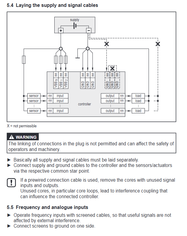
The power and signal grounding adopt star shaped single point grounding
Shielded wire single ended grounding
Wiring taboos
Prohibit internal short circuiting of plugs
Separate wiring for power and signal lines
Idle cores must be removed to prevent interference coupling
connector
55 pin locking connector, anti reverse connection
Supports crimping connections of 0.5~2.5mm ²
Input/output specifications
1) Input (16 channels, IN00~15)
Type: Analog (0~10V/0~20mA), Digital, Resistance (16 Ω~30k Ω), Frequency (≤ 30kHz)
Resolution: 12 bits
Digital threshold: conduction>0.7UB, turn off<0.3UB
Capable of diagnosing wire breakage/short circuit
2) Output (16 channels, OUT00~15)
Type: High side switch PWM (20~250Hz)、 Constant current, analog (0.2~10V)
electric current:
Conventional: 0.02~2A/channel
High power: 0.02~4A/channel (OUT 10~11)
Output group total current: continuous * * ≤ 9A * *, short-term ≤ 12A
Integrated inductive load continuous current protection
3) Communication interface
2-channel CAN 2.0B, ISO 11898
Baud rate: 50k~1Mbps (default 250k)
Protocol: CANopen, SAE J1939, Free Protocol
Software and Programming
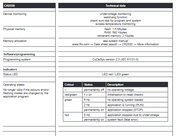
Development environment: CoDeSys 2.3, compliant with IEC 61131-3
Processor: Freescale PowerPC 50MHz
Storage:
Flash:1.5MB
RAM:592KB
Power down hold: 2KB
Built in monitoring: watchdog, program verification, over temperature, under voltage protection
Summary of Technical Parameters
Project parameters
Supply voltage 8~32VDC
Working temperature -40~85 ℃
Size 153 × 132 × 43mm
Weight 1.0kg
I/O total of 32 points (16 inputs/16 outputs)
Protection level IP67
Consumption current 50mA (24V)
Certification CE, E1, EN 61000, ISO 16750
Maintenance and Disposal
Maintenance free design, users are prohibited from opening and repairing the lid on their own
Scrap according to national electronic waste regulations
Warranty and Compliance: Modification will result in loss of warranty and liability
Key questions and answers
Question 1: How to configure the power supply and fuse of CR2530? What are the risks of connecting incorrectly?
answer
Power supply: 8-32VDC wide voltage, must meet SELV safety low voltage requirements
Three independent insurance options:
VBBS (sensor): ≤ 2A
VBB1/VBB2 (output): ≤ 15A
Risk: Connecting AC, reverse connection, and overpressure may directly damage the equipment; Lack of insurance can lead to overload and burnout.
Question 2: What are the I/O resources and typical application capabilities of CR2530?
answer
16 inputs: supports digital/analog/resistor/frequency, compatible with onboard sensors
16 output: supports high side/PWM/constant current, drives valves, lights, and motors
2-channel CAN: Implement in vehicle network communication (CANopen/J1939)
Suitable for integrated logic control of engineering machinery, commercial vehicles, and agricultural machinery.
Question 3: What are the 3 core mechanical/electrical rules that must be followed when installing CR2530?
answer
Mechanical: fixed with 4 × M5 screws, with the interface facing downwards, and the housing is not subjected to torque
Grounding: The shell is connected to the ground of the vehicle body, star shaped grounding, and shielded single end grounding
Wiring: power-off insertion and removal, cable separation, prohibit internal short circuiting of plugs