LTi DRiVES ServoOne single axis servo drive
Product basic information
Product positioning
Modular single axis servo drive, supporting bus communication and independent motion control, suitable for industrial equipment integration.
Specification coverage
Rated current: 4A -450A; Power supply: single-phase 230V/three-phase 230/400/460/480V AC.
model identifier
Order code SO8x.xxx.0xxx.xxxx. x defines voltage, current, safety, communication, cooling methods, etc; The serial number on the nameplate can be used to check the production year and month.
Standard Configuration
Drive host, terminal accessories, waterproof ring for liquid cooled models, product DVD.
Safety regulations (core mandatory requirements)
High Voltage Danger
After a power outage, if the capacitor still has power for ≥ 30 minutes, it must be confirmed that the voltage is less than 50V before operation.
personnel qualification
Only electrical professionals are allowed to operate and comply with IEC/DIN/VDE and local safety regulations.
Special population restrictions
Personnel with pacemakers and metal implants are prohibited from approaching the equipment and motor area.
compliance requirements
Must comply with the Machinery Directive 2006/42/EC, EMC Directive 2004/108/EC, and Low Voltage Directive 2006/95/EC.
Warning sign
Three types of warnings: high voltage, rotating components, and equipment damage caused by misoperation.
Mechanical installation
Installation environment
Vertically installed in the control cabinet, with reserved ventilation/water cooling space for air-cooled/liquid cooled models; Prohibit long-term vibration environment; When using cabinets with IP4x or higher, the STO function needs to be IP54+.
cooling method
Air cooling: forced convection, heat sink can reach 100 ℃
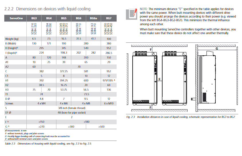
Liquid cooling: 3/8-inch internal thread interface, leak proof quick plug, coolant ≤ 40 ℃ and not lower than 10K in the environment, anti condensation
Size and fixation
Differentiate sizes, screw specifications (M4/M5/M8/M10), and installation spacing according to BG1-BG7 models; Multiple devices arranged side by side in power order to reduce thermal interference.
EMC installation
Good grounding metal installation plate, the paint surface needs to be scraped off the contact area; Filter and driver cable ≤ 30cm.
Electrical installation (core wiring)
1. Grounding (PE)
Star connection to the main grounding bar, leakage current>3.5mA, cable cross-sectional area ≥ 10mm ² or equal diameter to the power cord.
2. Power supply system
Control power supply: 24V DC ± 20%, connect the control power first and then use the main power to prevent misoperation.
Main power supply: shielded cable, must be equipped with B-type leakage protector; IT power grid is prohibited from use; BG5+forced inlet reactor.
Fuse: Match gG fuses according to the model, see attached table for details.
3. Overview of interfaces (by chassis BG1-BG7)
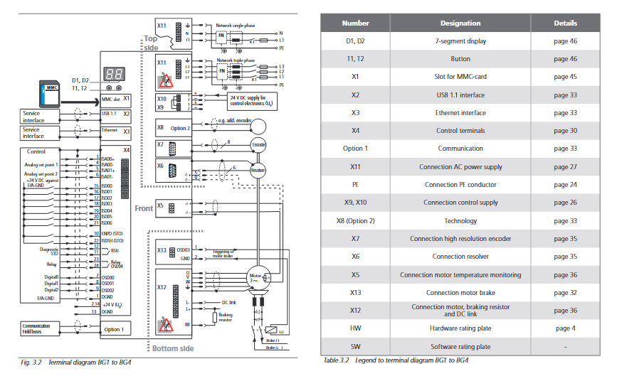
X9/X10/X44:24V control power
X11: Main power input
X12: Motor, braking resistor, DC bus
X4: Control terminals (digital/analog, STO, relay)
X2: USB 1.1 Debugging
X3: Ethernet 10/100M debugging
X6/X7: Encoder/Rotary Transformer
X13/X20/X44: Motor holding brake
X1: MMC storage card slot
4. Control terminals
Analog quantity: ± 10V, 12 bits
Digital quantity: 24V, ≤ 4.8V low/≥ 18V high
STO safety torque shutdown: ENPO (release)+ISDSH (request) dual channel, OSSD compatible, response ≈ 10ms
Relay/digital output: PLC compatible, short circuit protection
5. Encoder adaptation
Rotation → X6
SSI/EnDat/HIPERFACE/SinCos→X7
Original shielded cables must be used, and intermediate connections are prohibited
6. Motor and Brake
Shielded motor wires, grounded at both ends; PTC temperature protection connected to X5
Brake drive maximum 2A, high current requires external relay
7. Braking resistor
Feedback brake energy consumption and heat generation, choose between internal/external
External resistor needs to be connected to a temperature switch, and if it exceeds the temperature limit, the main power will be cut off
Different voltages correspond to different conduction thresholds (390/650/745/765/820V DC)
Debugging (Commissioning)
1. First debugging steps
Install DriveManager 5 software
Only power on 24V control power, complete initialization
USB/Ethernet connection to PC
Wizard configuration of motor parameters (LTi motor can download parameter library)
Power on, unlock STO, enable drive, no-load test
2. Panel operation (T1/T2 buttons+dual seven segment code D1/D2)
Status/fault code display
PA menu: Factory reset parameters, MMC card upload/download
IP menu: Ethernet IP/Subnet Mask Settings (default 192.168.39.5)
Fb menu: Bus address setting
MMC card firmware update: main. hex insert \ firmware \, power on and long press T1+T2
3. Batch debugging
Batch copy parameters through DriveManager or MMC card; The iPLC program requires CoDeSys download.
Diagnosis and faults
Panel status code
Display the status of reset, initialization, standby, running, emergency stop, fault, etc.
fault display
Er+fault number+location code, flashing repeatedly; It can be software cleared or power off reset.
Software diagnosis
DriveManager checks device status, the last 20 faults, and parameter 31 to view detailed alarms.
after-sales support
Provide the official German phone number, email address, and work order system, including model number, serial number, firmware version, fault code, and software version.
Safety Function: STO (Safe Torque Off)
The independent safety manual states that it meets EN ISO 13849 and achieves torque free safe shutdown without the need to cut off the main power supply.
Appendix Core Parameters
current capacity
Air cooling/liquid cooling, switching frequency (2/4/8/12/16kHz), and ambient temperature determine the rated/peak current, protected by I ² t.
Technical data
Output current, bus capacitance, braking power, losses, allowable cable length, EMC rating (C2 residential/C3 industrial) for each model.
environmental conditions
Working temperature -10-45 ℃ (air-cooled)/-10-40 ℃ (liquid cooled), altitude ≤ 2000m, pollution level 2.
Water cooling requirements
The coolant is chlorine free and calcium free, with impurities ≤ 15mg/d ³, pressure 1-2 bar, and flow rate 3-13L/min.
UL Certification
BG1-BG6a comply with UL 508C and BG7 planning; Specify copper wire, torque, and fuse.