Beckwith M-6280 Digital Capacitor Bank Controller
Product positioning and core applications
Core functions: automatic switching control of capacitor banks, remote scheduling, real-time electrical quantity monitoring, capacitor/switch fault detection, harmonic monitoring, fault recording, event timing recording;
Applicable scenarios: capacitors on overhead poles in distribution networks, parallel capacitor banks within stations, supporting electromagnetic/motor-driven switches;
Control logic: Supports automatic regulation of voltage/reactive power/current, compatible with local manual and remote SCADA scheduling, and has dual forced locking/switching logic for temperature and timing.
Standard configuration functions of the whole machine
(1) Three basic operating modes
Auto mode
Standard voltage control; Two expansion modes, reactive power VAr and current control, can be optionally selected;
Fixed time/inverse time delay, adjustable from 0 to 600s, timer supports instantaneous reset/integral reset;
Independent segmented setting of switching voltage, reactive power, and current thresholds, with fine and adjustable step sizes.
Remote mode
Send opening and closing instructions through communication, with built-in voltage upper and lower limit locking; If the operation exceeds the limit, refuse to execute and send an alarm; Voltage exceeding the limit can be automatically corrected by reverse switching.
Local Manual mode
Lock automatic and remote commands, with only panel buttons for opening and closing; For safety reasons, only voltage exceeding the limit is locked, and the voltage is not automatically corrected.
(2) Two types of forced override logic (effective in automatic mode)
Time override
You can set the effective start and end dates, time, duration, and repetition period, and force closing/opening/no action at the point.
Temperature override
According to the environmental temperature threshold, perform forced switching or holding above/below the set value.
(3) Capacitor switching timing delay parameter
All delays are independently adjustable and compatible with switch arc extinguishing and discharge safety requirements:
Closing warning delay: 0~90s; Opening warning delay: 0~90s;
Recloser interval: 300~600s;
Output pulse duration: Electromagnetic coil 50-100ms, motor drive 5-15s, customizable by type.
(4) Neutral point unbalanced current fault detection (core protection)
Used to determine capacitor unit breakdown, switch phase loss, and opening/closing failure:
Input specifications: Standard 200mA CT, optional 5A CT;
Two level fault threshold Level1/Level2, adjustable and disabled from 1.0 to 200A, with a fault delay of 10 to 300s;
Programmable after fault: retry operation, reverse disconnection, no action three choice logic;
Capacitor state criterion: If the neutral point current is greater than the fixed value, it is judged that the closing is in place; if it is less than the fixed value, it is judged that the opening is in place, with a confirmation delay. If the action fails, it can be automatically retried.
Optional access switch auxiliary contacts, A/B/C three-phase independent position feedback, and real-time display of on/off status on the interface.
(5) Real time measurement and harmonic analysis
Basic measurement: secondary voltage, differential pressure, neutral point current, frequency; After selecting the current module, it can measure three-phase primary/secondary current, active power, reactive power, apparent power, and power factor;
Transformer calibration: VT ratio and voltage offset correction; CT primary side magnification and neutral point current magnification can be adjusted in a wide range;
Harmonic analysis: Voltage and current harmonics up to the 31st order, synchronously calculate the total distortion rate THD; The accompanying CapTalk software can display real-time harmonic spectra.
(6) Counting and statistics function
Zeroable counter: records each opening and closing of the switch, supports resetting;
Permanent operation total counter: 0~999999 preset upper limit;
Daily operation frequency limit: 2-99 times, exceeding the limit will lock and switch on the same day with an alarm;
Both types of counters can be set with limit alarms, which can be output through communication or relays.
(7) Data recording function
SOE event sequence recording: stores up to 129 time stamped events, supports multiple conditions and/or triggers; Record opening and closing instructions, voltage exceeding limits, neutral point imbalance faults, harmonic exceeding limits, communication interruptions, self checking faults, SCADA heartbeats, etc.
Fault waveform recording
Cache voltage and current waveforms, with storage partitions 1-16 available for selection; Capture 321-2730 cycles of data after triggering, with a customized pre trigger/post trigger ratio of 5% -95%; Sampling rate of 16/32/64 points/cycle is optional; The trigger source is consistent with SOE.
Data Logging
Non volatile storage, continuously recording full operating data such as voltage, current, power, frequency, counter, capacitor status, etc. according to a set cycle, which can be exported through an SD card.
(8) Human computer interface and local operation
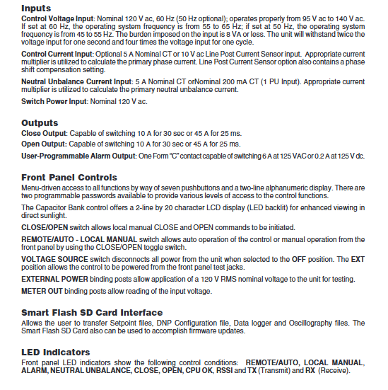
Display: 2-line x 20 character backlit LCD, visible under strong light; 7 shortcut keys for functions, two-level password permission management;
Panel physical switch: remote/automatic ↔ Local manual switching, voltage source OFF/INT/NEXT switching; External test power supply and measurement output terminal;
Status LED indicator lights: remote/automatic, local manual, alarm, neutral point imbalance, closing, opening, device normal OK, communication TX/RX, Bluetooth RSSI signal strength;
Smart Flash SD card slot: stores settings, waveform recording, logs, firmware upgrades, DNP configuration files.
(9) Standard communication capability
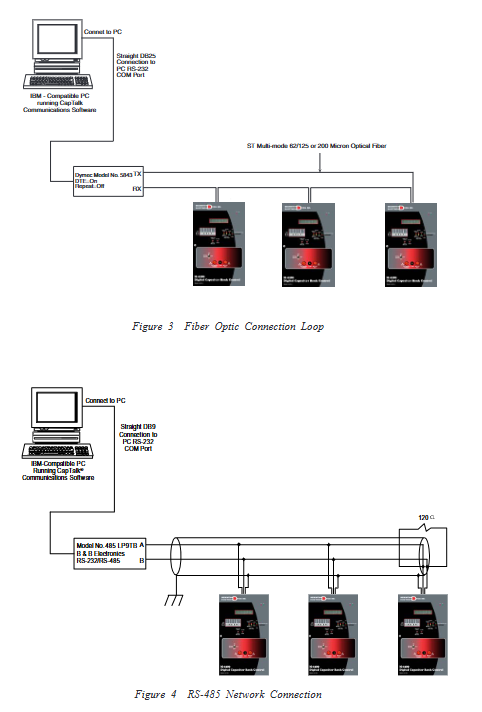
Hardware interface: USB, RS485/fiber ST; IRIG-B not mentioned;
Standard protocols: MODBUS, DNP3.0; USB local use MODBUS; DNP supports SCADA heartbeat messages;
Supporting upper software: CapTalk ® S-6280, Support fixed value reading and writing, waveform viewing, harmonic spectrum, remote broadcasting instructions, and abnormal alarm uploading.
(10) Output circuit
Closing and opening power output: short-term load of 45A for 25ms, long-term load of 10A for 30s, driving switch coil/motor;
Programmable alarm relay: 1 set of conversion contacts Form C, 125Vac 6A/125VDC 0.2A, can be output in linkage under any fault condition.
Optional expansion and optional features
Control mode expansion: 5A phase current CT input, line column current sensor (for reactive power/current automatic control);
Current detection expansion: 5A neutral point unbalanced CT input;
Communication Expansion:
RS232 serial port, Bluetooth V2.0 wireless (mutually exclusive with RS232);
10/100M RJ45 Ethernet or 100Base FX fiber optic Ethernet; Support MODBUS TCP, DNP3 TCP/UDP; Up to 8 concurrent connections, with a maximum of 5 sessions for DNP and 8 sessions for MODBUS, supporting DHCP/static IP;
Equipped with M-3801D waveform analysis software (CapTalk unified processing and waveform analysis in the article).
Electrical input hardware parameters
Control voltage input: nominal 120Vac 50/60Hz, working range 95-140Vac; 60Hz models have a frequency of 55~65Hz, while 50Hz models have a frequency of 45~55Hz. The load is ≤ 8VA, and the short-term withstand voltage is 2 times for 1 second and 4 times for 1 cycle.
Phase current input: Optional 5A CT or 10V column mounted current sensor with phase compensation.
Neutral point unbalanced current: standard 200mA CT, optional 5A CT.
Switching power supply: nominal 120Vac.
Environment, safety regulations, and electromagnetic compatibility
Working temperature: Whole machine -40 ℃~+85 ℃; LCD display effective range -20 ℃~+70 ℃;
Damp heat durability: IEC 60068 high and low temperature, 40 ℃ 95% RH wet heat cycle;
Insulation withstand voltage: All terminals are grounded at 1500Vac for 1 minute, and the circuits are electrically isolated;
Surge immunity: compliant with IEEE C37.90.1 2002/19892500V oscillating surge and 4000/5000V fast transient pulse;
EMC anti-interference: IEC 60255-22-4 4kV 5kHz fast pulse train; Radiation anti-interference to resist interference from handheld communication devices;
Shell protection: NEMA 4X polycarbonate flame-retardant shell, UV resistant, can be padlocked and sealed.
Physical dimensions and installation method
Overall shell size: 11.75 “W x 15.75” H x 7.25 “D (29.9 x 40 x 18.42cm), net weight 4.1kg;
Internal movement size: 9.18 “W x 15” H x 3.22 “D (23.32 x 12.5 x 8.18cm);
Installation methods: pole mounted installation, metering socket base installation, multi pin aviation plug wiring, integrated metering cabinet base adaptation;
Terminal definition: The document comes with a complete external wiring diagram, including voltage CT、 Switching output, switch auxiliary contacts RS485、 Alarm contacts, etc.
Communication networking solution
The document provides 5 typical networking topologies:
USB direct connection to PC for local debugging;
RS485 two-wire bus multi unit network;
ST fiber optic loop networking;
Ethernet RJ45/fiber optic switch LAN;
RS232 external cellular 4G/EDGE/GPRS/CDMA remote wireless scheduling;
Device address range: MODBUS 1~247, DNP3.0 1~65519, supports broadcasting command issuance.