DEIF AGC-4 Mk II Generator Set Controller
Standard Functions and AC Measurement System of the Whole Machine
Standard core functional modules
Operation mode system: AMF mains backup, isolated grid independent, fixed base load, peak shaving, load transfer, and mains reverse power transmission six standard single machine modes;
Engine full timing control: standardized start, idle, cooling stop, emergency stop logic, supporting dual start motors, preheating and pre lubrication;
ANSI standard complete protection: generator side+busbar side independent timed protection;
Human Machine Unit DU-2: Remote installation display screen with start stop and on/off buttons, optional TDU touch screen;
M-Logic has built-in programmable logic: a simple PLC without code, which realizes interlocking, constant value switching, and relay linkage through events and commands.
AC communication measurement configuration (menu 9130)
The controller supports three types of power grid measurement architectures and can be switched with one click:
Three phase system (factory default): Three phase three wire/four wire, suitable for 400V low voltage, high voltage requires external PT voltage transformer, separate generator and busbar two sets of transformation ratio parameters;
Phase separation system (American standard 120/240V): L1-L3 phase difference of 180 °, independent alarm logic for phase voltage;
Single phase system: single-phase measurement with neutral wire;
Reactive power calculation mode (parameter 9132): Line voltage calculation/phase zero voltage calculation can be selected, and when IEEE 1547 grid protection is enabled, it is forced to switch to phase zero algorithm.
Rated parameter group: The whole machine stores 4 sets of rated voltage/frequency/power parameters, which can be switched with one click through the panel, digital input, and M-Logic, suitable for mobile power stations and multi condition units; Support voltage range scaling, covering high and low voltage systems ranging from 10V to 250kV.
Mainstream standard application conditions (with principle curve and single line diagram attached)
There are a total of 12 basic applications, each including automatic/semi-automatic/manual logic and power ramp curves:
AMF has no synchronous switching back; 2. AMF with synchronous grid connection returning to the mains power supply; 3. Solitary network operation; 4. Active power ramp up and down; 5. Reactive Q slope; 6. Fixed foundation load; 7. Warm up power limit ramp; 8. Peak shaving operation; 9. Load transfer LTO; 10. Constant power transmission to the mains power MPE; 11. Collection of mains power transmitter; 12. Collection of reactive power/voltage transmission from mains power.
External 4-20mA transmitter collects the incoming power of the mains for peak shaving and load transfer control.
Five major controller operating modes
Semi automatic: automatic voltage and frequency regulation, synchronization, manual command for start/stop/opening/closing;
Not in auto: Non automatic state alarm output;
Test mode: divided into simple/loaded/full process testing, with the ability to set the testing duration and load, and automatically restore the original mode upon completion;
Manual: Turn off automatic adjustment, only manually jog speed and pressure regulation, opening and closing, without synchronous locking;
Block locking mode: exclusively for maintenance purposes, prohibits automatic start-up, shuts down the operating unit upon disconnection, shields automatic processes, and only retains alarm monitoring.
Full process control flowchart
The document provides dozens of standardized timing diagrams: mode switching, mains power on/off, generator on/off, start/stop AMF、 Peak shaving, load transfer, testing the entire process sequence, clearly label each timer, trigger condition, and fault jump branch.
Standardized timing sequence for start stop and circuit breaker
Start up process: pre lubrication/preheating delay, multiple start-up attempts, multiple operation feedback of speed/oil pressure/frequency, and logic for disengaging the starting motor; Support temperature controlled idle start;
Shutdown process: Normal shutdown with cooling, emergency shutdown without cooling, distinguishing between protection tripping, manual shutdown, and remote shutdown;
Circuit breaker timing: Generator GB, mains MB, bus tie TB opening and closing logic, spring energy storage delay, synchronous locking, overlapping parallel delay, maintenance extraction locking function;
AMF dedicated timer: mains voltage loss delay, recovery confirmation delay, opening and closing buffer delay, with voltage/frequency hysteresis to prevent misoperation.
Single machine Application without Power Management
Application of Single Line Atlas
Includes standard primary diagrams for AMF, isolated grid, base load, peak shaving, load transfer, mains power transmission, and simulated load sharing (M12 hardware option).
CANshare digital load sharing (without PMS, only isolated network with multiple machines)
Applicable scenarios: No mains power, multiple units connected in parallel in isolated networks, CAN bus digital equal distribution of active/reactive power; Support AGC-4 Mk II and AGC150 hybrid;
Configuration method: USW software or panel quick setting, automatically identifying the same bus controller;
Operating characteristics: Automatic splitting and independent sharing of single disconnection, bus fault alarm, support for M-Logic cross unit exchange of switch value flag bits;
Fault handling: If the bus is lost, the unit operation mode can be switched.
PMS Lite Simple Power Management (pure off grid multi unit, no mains/bus connection)
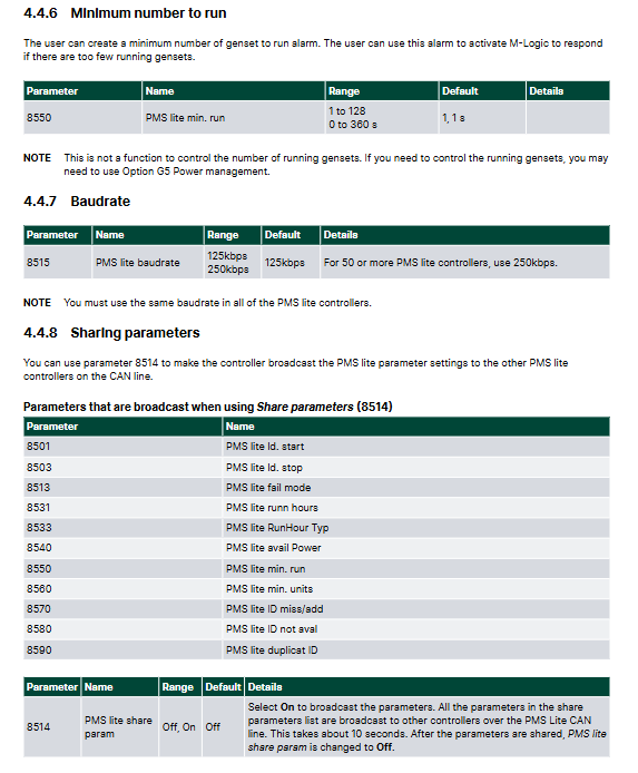
Positioning: Simplified version of multi machine isolated network system, no need for upper level software, configuration can be completed on the panel, up to 127 units;
Core functions: load linkage start stop LDSS, unit priority rotation, running hour balancing, minimum running unit alarm, parallel black start for multiple units;
PLC external control mode: It can be connected to an external PLC to take over the start and stop of the unit, and shield the automatic logic of the load;
The complete mechanism includes automatic broadcasting of CAN bus parameters, communication fault alarm, and ID duplicate/missing alarm.
Power Management with Complete PMS (G5/G7 Options)
Multi topology single line diagram
Covering multiple units in a single grid, combining units with mains power, multiple incoming mains power lines, ATS automatic switching, bus segmented BTB, photovoltaic/energy storage hybrid energy, and remote operation and maintenance system.
PMS core capabilities (G5 standard, G7 extended to 32 or more units)
Multi type controller collaboration: unified CAN bus scheduling for generators, mains power, bus tie, energy storage ASC, and load ALC;
Load distribution, automatic replacement of faulty units, interlocking of segmented busbars;
Power grid faults, islanding switching, and coordinated charging and discharging control of energy storage;
Complete communication failure, offline unit, and ID conflict handling logic.
Complete Standard Time Limited Protection (ANSI Specification)
All protections are timed logic: start timing when the measurement exceeds the limit, automatically reset when the value drops, and execute preset fault level actions (alarm/circuit breaker tripping/shutdown) when the time exceeds.
Phase sequence/phase rotation protection: Independent monitoring of generator, mains, and bus tie voltages, distinguishing the action logic of single/multi machine systems;
Demagnetization protection 40: Monitor the compatibility reactive power of the generator, set the threshold based on the generator capacity curve to prevent demagnetization and step loss;
Low voltage current limit (51V): When the short-circuit voltage drops, the overcurrent setting is automatically reduced to solve the problem of insufficient low-voltage short-circuit current and inability to trip. It supports a 6-point voltage current custom curve;
Three phase current imbalance protection: two calculation modes (maximum difference method, average deviation method) to prevent single-phase winding overheating;
Three phase voltage imbalance protection: suitable for capacitor compensation and single-phase load fault scenarios;
Overexcitation protection: limits the inductive reactive power output of the generator, and the C2 option can enable complete generator P-Q capacity curve protection;
Voltage measurement reference switching: Supports global switching of line voltage/phase zero voltage, synchronously modifying all protection judgment references.
PID Control System for Speed/Voltage Regulation
General Principles of PID
The proportional Kp, integral Ti, and differential Td are independently adjustable in three loops, which are used for frequency, active power, voltage, and reactive power closed-loop respectively; The document provides formulas, adjustment curves, and tuning guidance.
Six specialized PID controllers
Frequency PID (isolated network basic speed regulation);
Active power PID (grid connected base load);
Active power sharing PID (multi machine parallel);
Voltage PID;
Reactive power/power factor PID;
Reactive power sharing PID.
Two ways to adjust output
Analog ± 20mA continuous adjustment;
Relay pulse point-to-point adjustment, setting dead zone and pulse period to avoid frequent operation of the contactor.
Droop adjustment function
0~10% adjustable frequency/voltage difference, suitable for old-fashioned differential parallel units; Support dynamic frequency adjustment, suppress low load/reverse power in photovoltaic isolated grid scenarios.
Complete Control Logic for Simultaneous Grid Connection
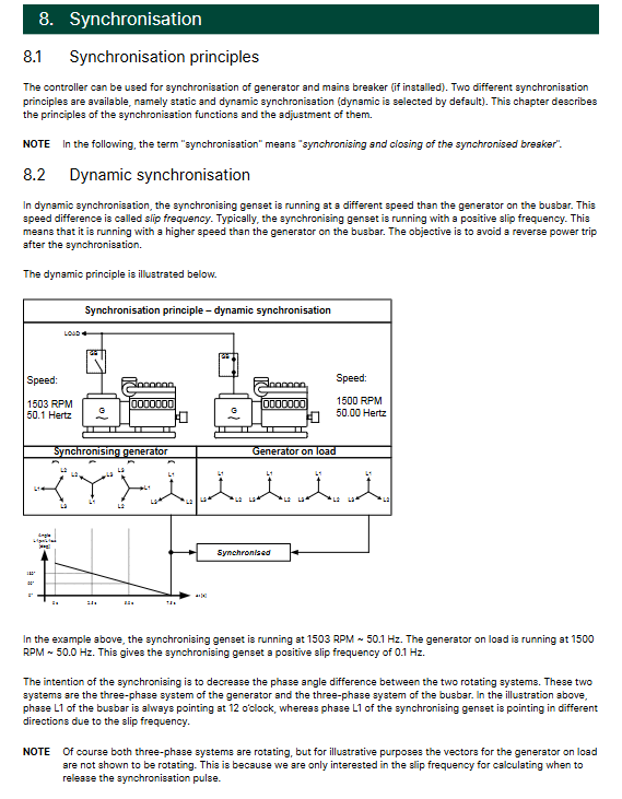
Dynamic synchronization (default)
The generator is equipped with a small forward sliding frequency to catch up with the busbar, compensating for the delay of circuit breaker closing and outputting closing pulses in advance, greatly reducing the impact of grid connected reverse power. The maximum/minimum frequency difference, voltage difference, and closing advance angle can be customized.
Static synchronization
Extremely low sliding frequency, fine phase PI adjustment, zero impact grid connection, suitable for no-load and light load scenarios, relay adjustment mode is not recommended.
CBE special mode of first closing the circuit breaker and then starting the excitation
Transformer soft start dedicated: first close the generator circuit breaker and then establish the voltage, supporting a complete set of timing for speed threshold, excitation delay, and fault alarm, and providing two standard flowcharts.
Simultaneous locking conditions
Black start voltage threshold, digital input prohibited for closing, delayed lockout for mains power recovery, and independent synchronous relay expansion function.
Extensive Expansion of Auxiliary Functions
Engine start stop matching: Multi type speed acquisition (MPU magnetic pickup, ECU engine bus, oil pressure feedback), dual start motor rotation, low-temperature idle, engine insulation heater;
Cooling fan control: up to 4 sets of fans, started and stopped in stages according to water temperature, balanced operating time, and fan fault alarm;
Derate of Unit Capacity Reduction: Water temperature, ambient temperature, ECU overload signal trigger power limit, supporting proportional/inverse capacity reduction curves;
DFR dynamic frequency response: adapted to photovoltaic energy storage isolated grid, automatically raising the frequency when the photovoltaic output is too high, suppressing low load and reverse power of the generator;
Non critical load tripping in NEL classification: Secondary loads are cut off in stages during low frequency and unit overload to prevent power loss throughout the entire station;
Pump group logic: automatic start stop of fuel pump, urea DEF pump, universal fluid pump liquid level, liquid shortage alarm;
Simulated load sharing (M12 hardware): -5~+5V simulated bus parallel with old units, backup sharing channel in case of CAN failure;
Maintain timing, oil change timing, and timed automatic start stop commands;
Trip circuit monitoring, periodic battery testing, cabinet door lock locking, and configuration of step-up/step-down transformer vector groups;
Event recording, 500 alarm storage, TCP/IP Ethernet NTP synchronization.
General External PID
Independent 4-20mA analog PID closed-loop, can be connected to third-party devices such as temperature and pressure, paired with M-Logic linkage, used for external control of boilers and cooling systems, supporting gain compensation and dynamic input switching.
Chapter 10 Input/Output IO System
Digital DI input: more than 50 programmable functions (start stop, mode switching, synchronization permission, fault feedback, etc.), disconnection detection;
Multi input: 4-20mA, 0~40V, Pt100/1000, resistance sensor (oil pressure/water temperature/liquid level);
Simulated AO transmission: active/reactive/voltage/frequency programmable 4-20mA output;
Relay output distinguishes between alarm, control, and limiting contacts, providing AC/DC breaking capacity parameters;
Differential measurement, external simulation given access specifications.