Installation Manual for DEIF BRW-1 Marine Wing Bridge Instrument
Product Core Features
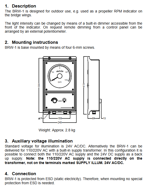
Protection level IP66 waterproof and dustproof, suitable for outdoor marine environments;
The backlight system features long-lasting LED lighting, and the black dial is equipped with independent pointer backlighting; Comes with a built-in panel dimming potentiometer, supporting remote dimming with an external potentiometer;
The human-machine design features a large-sized and wide dial with clear readings;
Electrostatic protection: The whole machine is equipped with ESD protection, and no additional anti-static measures are required for installation;
Ship compliance: Meet the safety distance of ship compasses and the EMC electromagnetic compatibility standards for ships.
Mechanical installation specifications
Fixed method: base type installation, fixed with 4 6mm screws; The total weight of the machine is about 2.8kg;
Attention to disassembly and assembly: When disassembling the dimming panel and instrument frame, it is strictly prohibited to damage the internal silicone seals (waterproof key);
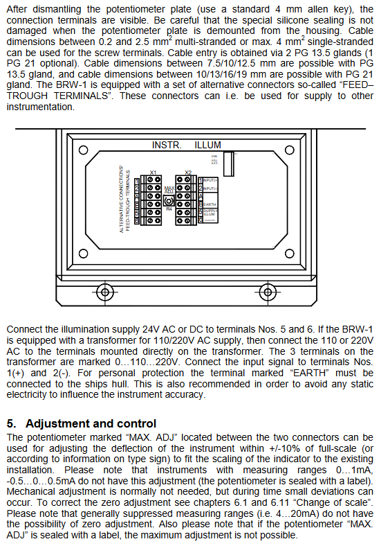
Cable entrance configuration: Standard configuration includes 2 PG13.5 cable glands, optional PG21 gland;
PG13.5 is compatible with cables with an outer diameter of 7.5/10/12.5mm;
PG21 adapter cable outer diameter 10/13/16/19mm;
Terminal cable specifications: Multi strand wire 0.2~2.5mm ², single strand wire up to 4mm ², also compatible with 26AWG thin wire;
FEED-TROUGH TERMINALS: Supports one incoming line and multiple outgoing lines, can be connected in series to supply power to other instruments, simplifying wiring inside the ship.
Lighting power supply scheme (two versions)
Scheme 1: Standard 24V AC/DC Lighting
Lighting terminals 5 and 6 are connected to 24V AC/DC, with power consumption of 150mA for white background dial and 300mA for black background dial.
Option 2: Built in transformer 110/220V AC version
Connect 110/220V AC directly to the independent terminals of the transformer (0/110/220), without connecting to the 5 and 6 lighting terminals;
Support dual power supply redundancy: Transformer 110/220V main power+24V AC/DC backup lighting are connected simultaneously.
Definition of wiring terminals (X1/X2 terminal block)
INPUT (+)/INPUT (-): Measure positive and negative input signals (standard analog signals such as 0~1mA/4~20mA);
Supply ILLUM 5/6:24V AC/DC lighting power supply;
DIM ADJ. EXT: External remote dimming potentiometer interface;
MAX ADJ: Full range fine adjustment potentiometer;
EARTH grounding terminal: forcibly connected to the ship’s hull, ensuring personal safety and eliminating static interference to ensure measurement accuracy;
Through terminal: can be connected in series with other marine instrument power circuits.
Instrument calibration and adjustment
1. Full range adjustment (MAX ADJ potentiometer)
Can correct scale deviation within ± 10% of full range and adapt to on-site signal matching;
Limitations: The potentiometer of instruments with ranges of 0… 1mA, -0.5… 0.5mA is sealed and locked, and cannot be adjusted; 4~20mA offset range without zero adjustment function.
2. Mechanical zero calibration
When using the pointer offset for a long time, disassemble the panel and move the front fork of the moving coil to perform mechanical zeroing.
Complete steps for replacing the dial
The original factory pre installs the scale according to the order and supports on-site replacement of the scale. The complete disassembly process is as follows:
Remove the 4 screws from the frame, remove the aluminum frame and glass, and protect the silicone seal ring;
Remove the four corner fixing screws of the scale;
Loosen the bottom fixing screws of the PCB circuit board, lift the circuit board and disconnect the wiring;
Remove the center screw of the scale and extract the old scale;
Install new scales, reverse restore PCB and borders;
Calibrate the mechanical zero point of the pointer after completion.
Complete technical specifications
Accuracy level: 1.5 level, in compliance with EN 60051 and IEC 51 standards, suitable for environments ranging from -10 ℃ to+55 ℃;
Electrical isolation: 2kV 50Hz withstand voltage for 1 minute;
Compass safety distance: 1 meter (limited by marine magnetic interference);
EMC standards: EN50081-1/2, EN50082-1/2, marine SS4361503, IEC 60522;
Shell material: ABS/PC flame retardant alloy, UL94 V0 self extinguishing grade;
Protection: IP66 (IEC529/EN60529);
Insulated terminal: screw type terminal block.
Important safety and operational points
Grounding mandatory requirement: The EARTH terminal must be reliably connected to the ship to prevent reading errors caused by electric shock and static drift;
Sealing protection: All disassembly and assembly operations must not damage the silicone waterproof seal of the instrument, otherwise it will lose IP66 protection;
3 Power supply differentiation: The 110/220V transformer model does not connect to the 5/6 lighting terminal, and the two are independent circuits;
Adjustment permission: Seal and lock the range potentiometer to prevent unauthorized adjustment, otherwise the accuracy will be invalid;
Ship adaptation: meets maritime equipment certification and is suitable for high humidity and salt spray ship operating conditions on outdoor wing bridges.