ADLINK NuPRO-E42 PICMG1.3 full-length SHB motherboard
Product Overview and Core Positioning
1. Product form
Standard PICMG 1.3 full-length SHB industrial motherboard, relying on the chassis backplane to provide PCI/PCIe expansion slots, separates the computing motherboard from the expansion backplane, suitable for high-density expansion of industrial control platforms with multiple acquisition cards and vision cards.
2. Core hardware platform
-CPU: LGA1150 slot, supports 4th generation Intel i7-4770S/i5-4430S/i3-4330S/Pentium G3420;
-Chipset: Intel Q87 PCH, supports PCIe 3.0, RST disk array, AMT9.0 remote management;
-Memory: Dual channel DDR3 1333/1600, dual 240pin DIMM, maximum 16GB;
-Positioning: High scalability industrial control, machine vision, high-speed DAQ testing equipment, server level industrial control.
3. Core functional highlights
1. Rich industrial I/O: 6 serial ports (1 programmable RS232/422/485), 12 USB ports (6 × USB3.0), dual gigabit network;
2. Storage: 4 x SATA 6Gbps, supporting RAID0/1/5/10;
3. Expansion: The motherboard leads out PCIe x16 graphics card slots, and the backplane provides 4PCI+4PCIe x1;
4. Security: TPM 1.2 hardware encryption, hardware watchdog, hardware voltage/temperature/fan monitoring;
5. Remote: Intel AMT 9.0 out of band management PXE、WOL;
6. Display: Onboard VGA+pin type DVI dual display, integrated Intel HD core display;
7. System: Supports Windows XP/7/8/Server 2008 and Ubuntu Linux.
Complete hardware specifications and parameters
1. Operations and Storage
– CPU TDP:i7 65W、i5/i3/Pentium 54W, The motherboard is equipped with a temperature controlled fan;
-SATA: 4-channel 6Gbps, AHCI/RAID dual-mode;
-Audio: Optional DB-Audio2 daughter card for HD audio;
-Storage Expansion: Only supports 2.5-inch SATA hard drives, without onboard CF/M.2.
2. Network interface
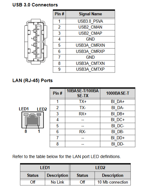
Dual Gigabit Ethernet:
– LAN1:Intel I217LM, Supports AMT9.0, PXE, WOL;
– LAN2:Intel I211AT, Industrial gigabit, supporting giant frames IEEE1588。
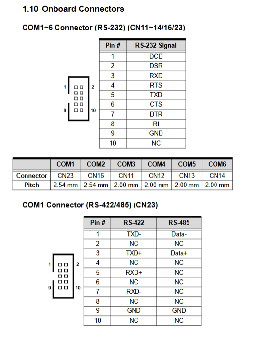
3. Serial COM (6 DB9 pins in total)
-COM1: Dial SW13 to switch RS232/422/485;
-COM2~6: Fixed RS232;
-All serial ports support BIOS serial console redirection and remote operation and maintenance.
4. USB resources
-Rear panel: 2 x USB 3.0;
-Onboard pins: 4xUSB3.0, 4xUSB2.0; A total of 12 USB ports.
5. Display output
1. Rear DB15 VGA (analog output);
2. Onboard 20 pin DVI-D pin, optional matching baffle adapter for DVI display;
3. The integrated core display supports multiple screens, and the BIOS can set priority startup for the display device.
6. Environment and Electrical
-Working temperature: 0-60 ℃; Storage -20~80 ℃;
-Humidity: 10%~90% without condensation;
-Safety regulations: CE/FCC A-class industrial certification, RoHS compliance;
-Power supply: Standard ATX 12V main power supply, motherboard 24pin+4-pin power interface.
7. Power consumption reference (measured at full load)
-The i7-4770S has a full load capacity of approximately 86W;
-The i5-4430S has a full load capacity of approximately 54W;
-S3 standby power is only 0.6~0.8W, S5 shutdown power is 0.4~0.5W.
Overall I/O layout (rear panel+onboard pins)
1. Rear baffle interface (exposed)
2 x RJ45 Gigabit Ethernet, DB15 VGA, 2 x USB 3.0.
2. The motherboard is equipped with built-in pins (which need to be led out with matching cables)
1. 6-way COM serial port terminals (with two spacing options of 2.54mm/2.0mm);
2. DVI-D video pin;
3. 4-channel SATA power supply+data;
4. CPU fan FAN1, system fan FAN2 (4-pin PWM speed regulation);
5. HD Audio sub card socket;
6. PS/2 keyboard and mouse pins;
7. System panel pins (power button, reset, hard disk light, buzzer);
8. Clear CMOS jumper JBAT1 and RTC jumper JBAT2;
9. Expansion pins for 12V auxiliary power supply, I2C bus, etc.
3. Dial switch SW13
Control only COM1 communication mode:
– 1ON+2OFF:RS232
– 1ON+2ON:RS422
– 1OFF+2ON:RS485
Hardware installation process
1. CPU installation specifications
LGA1150 locking slot, operation points:
1. Press down to unlock the lever, flip over the load board, and remove the protective cover;
2. Align the CPU triangle with slot Pin1 and do not press it forcefully;
3. Buckle the load plate and lock the lever;
4. It is necessary to apply thermal grease and install a cooling fan, as the absence of a fan will burn out the CPU.
2. Memory installation
Dual channel DDR3, two memory capacities/brand recommendations are completely consistent; The slot buckle opens outward, aligning the memory gap and automatically locking when inserted. The single/dual channel mode BIOS automatically recognizes it.
3. Driver installation sequence (Windows system)
1. Intel Q87 chipset driver;
2. Integrated graphics card driver;
3. Dual network card driver;
4. Intel ME Management Engine;
5. USB 3.0 controller;
6. Optional RST disk array driver (loaded by F6 during system installation).
Complete AMI Aptio BIOS setup manual
Press’ Del ‘to enter BIOS during startup, which is divided into 7 main menus with all graphic and textual configuration instructions:
1. Main page
Display BIOS version, CPU/memory information, system time, and access permissions.
2. Advanced (Core Configuration Area)
1. ACPI: sleep mode (S1/S3), power-off and power on behavior;
2. Trusted Computing: TPM 1.2 switch, key clearing;
3. CPU configuration: number of cores, VT virtualization, XD protection, energy-saving strategy;
4. SATA: IDE/AHCI/RAID mode switching, hot plugging;
5. TXT secure execution technology;
6. DVMT memory allocation and multi screen settings for graphics cards;
7. USB: Traditional DOS compatible, XHCI/ehci switch;
8. Super IO: 6-way serial port switch and parallel port configuration;
9. Hardware monitoring: CPU/board temperature, fan automatic speed regulation curve;
10. AMT out of band management switch;
11. Serial console redirection (remote operation and maintenance).
3. Chipset chipset
-Priority of integrated graphics card/discrete graphics card startup;
-PCIe port channel splitting (single x4 or 4-channel x1);
-Enable network card and audio controller;
-Power off and restore the power on state setting.
4. Boot startup
Start device priority, PXE network boot, boot NumLock, full screen Logo switch.
5. Security Security
Administrator/user two-level boot password and Secure Boot related settings.
6. Save & Exit
Save/discard modifications, load optimal/fault defaults, temporarily start device reload.
Hardware watchdog WDT
1. Function: 1-255 seconds/1-255 minutes timeout optional, automatic machine reset after timeout;
2. Bottom layer implementation: ITE IT8783 Super IO chip;
3. The document comes with complete DOS C source code and provides register read and write examples;
4. WDT can be turned on/off in the BIOS, and the system software supports regular dog feeding.
System underlying resources (essential for development)
Complete list of motherboard hardware underlying allocation table:
1. Memory address mapping (BIOS, APIC, VRAM, SMM area);
2. DMA channel occupancy allocation;
3. I/O port base address (serial port, SIO, SATA, PCI controller);
4. Interrupt routing for all IRQs in PIC/APIC modes;
5. PCI bus device number and interrupt sharing mapping table;
Used for driving, low-level data collection, and real-time system development.
Safety and packaging
1. Standard packaging
NuPRO-E42 motherboard, SATA data cable, USB 3.0 dock cable, 6-way serial port matching cable, driver DVD, paper manual.
2. Safety regulations
-The ATX power supply must be disconnected when disassembling or plugging in the card;
-The motherboard is equipped with a CR2032 lithium battery, and there is a risk of explosion if the wrong model is replaced;
-Static electricity protection: disassemble and wear a grounded anti-static wristband;
-High temperature conditions require the use of original 4-pin temperature controlled fans.
3. Environmental compliance
Compliant with EU RoHS and WEEE waste electronic recycling standards, the entire machine does not contain restricted heavy metals.