ADLINK NuPRO-865 Full length Single Board Computer
Product Introduction
1.1 Open box counting and electrostatic safety regulations
Standard packing accessories
NuPRO-865 motherboard, installation guide, driver CD
ATA100 hard drive cable, floppy drive cable, print/COM1 serial port cable, USB harness, SATA power data cable, PS/2 keyboard and mouse Y-shaped cable, 4pin ATX control cable, 5-to-6-pin keyboard and mouse extension cable
Optional accessories: IP-ALCS20 audio sub card+9-pin audio ribbon cable; OEM customized version accessories will be added or removed as needed
Mandatory anti-static warning
Motherboard CPU、 Memory is sensitive to static electricity, and operations must use anti-static bags and grounded anti-static wristbands. Chips can only be inserted and removed on the anti-static workbench, and bare hands are prohibited from touching gold fingers.
1.2 Core Hardware Features
Processor platform
478 pin FC-GGA slot, supports Intel Pentium 4/Celeron, up to 3.2GHz; Front end bus 400/533/800MHz; Intel 865G+ICH5 chipset.
Memory
Dual 184 pin DDR DIMM slots, up to 2GB, compatible with DDR266/333/400.
Display
The onboard Intel Extreme Graphics 2 integrates AGP8X graphics card, with optional frame cache of 1/8/16MB.
Internet
Intel 82547GI Gigabit Ethernet card, 10/100/1000M adaptive.
Storage interface
2-channel SATA (150MB/s), 2-channel ATA100 IDE, 1-channel FDC floppy drive interface.
I/O peripherals
2 RS232 serial ports, 1 parallel port, 4 USB 2.0 ports, PS/2 keyboard and mouse, hardware watchdog WDT, hardware monitoring (temperature/voltage/fan speed); AC97 audio requires the optional IP-ALCS20 daughter card.
Industrial supporting functions
Long life cycle component selection, hardware monitoring, IRDA infrared pins, PCI+ISA expansion bus, suitable for harsh industrial environments.
1.3 System diagram and overall specifications
System architecture diagram
GMCH 865G North Bridge docking CPU, memory VGA、 Gigabit Ethernet; ICH5 Nanqiao manages SATA, IDE, USB, PCI buses; W83627HF Super I/O is responsible for serial/parallel/floppy drive/keyboard and mouse; The bridge leads to ISA and PICMG expansion slots.
Physical Specifications
The total length SBC size is 13.3 “× 4.8” (338 × 122mm), with a net weight of 420g. It adopts Award plug and play BIOS and battery power to save CMOS configuration.
Hardware installation
This chapter provides a complete explanation of the installation steps for CPU, heat sink, memory, jumpers, connectors, and audio daughter cards, with an attached board layout diagram.
2.1 Disassembly and assembly process of core components
CPU installation/removal
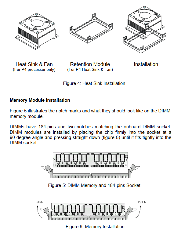
478 ZIF slot operation steps: Pull up the pressure rod, align the CPU foolproof notch, and press the lock buckle; Equipped with a dedicated P4 heat sink bracket, it is prohibited to use ordinary desktop CPU heat sinks (which can damage the motherboard); Before disassembly, the power must be cut off for cooling to prevent high-temperature burns.
Installation of memory DIMM
184pin DDR memory with dual notch fail safe, holding the edges with both hands to avoid touching the gold fingers, and the two end buckles automatically lock; Disassembly requires opening the plastic buckles on both sides; Idle memory must be stored in anti-static bags.
2.2 Jumper Function Definition
Only 2 sets of key jumpers, 3-pin cap short circuit structure:
JP1 (Clear CMOS)
Default 1-2 short circuit (normal operation); Short circuiting 2-3 for 5 seconds can clear BIOS configuration and restore factory settings.
JP2 (watchdog WDT)
Default 2-3 short circuit (system reset); Short circuiting 1-2 is in NMI interrupt mode.
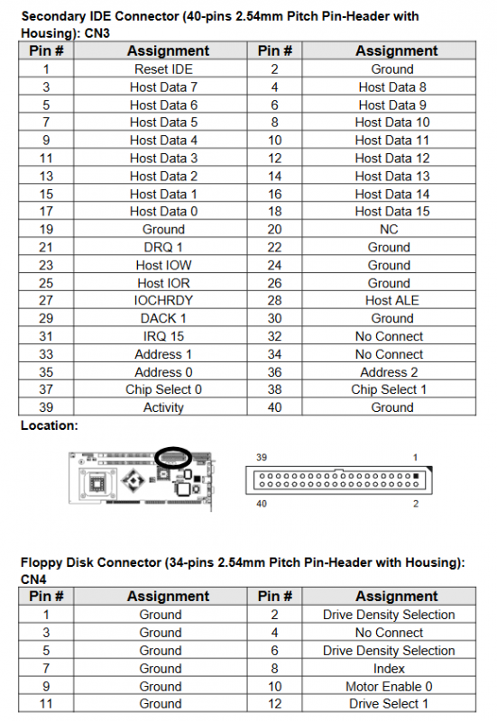
2.3 Definition of all connector pins (CN1~CN19, SATA1/2)
The manual lists the pin signals of all onboard pins and rear panel interfaces one by one, including:
CN1: Chassis panel (power light, reset, hard drive light, speakers, power switch)
CN2: ATX 12V auxiliary power supply; CN3/6: Primary and Secondary IDEs; CN4: floppy drive; CN5: Infrared IRDA
CN8/9: CPU fan, system fan speed measurement power supply; CN10/11: COM2/COM1 serial port
CN14: RJ45 Gigabit Ethernet port; CN17:15 pin VGA; CN19: Rear PS/2 keyboard mouse
CN16:9-pin AC97 audio pin (compatible with IP-ALCS20 daughter card); Two SATA hard drive interfaces
2.4 Optional accessories: IP-ALCS20 audio daughter card
Accessories list: Audio sub card, 9-pin audio ribbon cable
Onboard interfaces: JP1 (CD audio input), CN1 (microphone/line input/output 3.5mm jack), CN2 (docking with motherboard AC97 pin); Connect the motherboard CN16 through a ribbon cable to achieve onboard audio output.
Award BIOS Settings
Using Phoenix Ward BIOS, all settings are stored in the CMOS battery and will not be lost in case of power failure; Support fault safety default, optimized factory default, and graded password management, with a total of 15 setting submenus.
3.1 Overview of BIOS Main Menu
Standard CMOS Features: Basic system time, hard drive, floppy drive, memory, boot error strategy
Advanced BIOS Features: CPU characteristics, boot sequence, hyper threading, virus protection, serial console redirection
Advanced Chipset Features: Memory timing, AGP graphics memory, onboard graphics card switch, memory holes (ISA compatible)
Integrated peripherals: IDE/SATA, USB, AC97 audio, serial parallel port, power on/off recovery strategy
Power Management Setup: ACPI energy-saving, hard disk sleep, CPU temperature control frequency reduction, network/ringing power on
PnP/PCI configurations: PCI interrupt allocation, ESCD resource reset, VGA palette listening
PC Health Status: Hardware Monitoring Panel (CPU/System Temperature, Fan Speed, Various Voltage, Overheating Shutdown Threshold)
Frequency/Voltage Control: PCI clock, spread spectrum modulation
Tools menu: Load Fault Safety Default, Load Optimization Factory Default, Administrator/User Password, Save/Discard Exit
3.2 Key Menu Core Function Description
Standard CMOS
Automatically detect IDE/SATA hard drives, set floppy drive types, startup error and shutdown rules, and display basic/expanded/total memory capacity.
Advanced BIOS Features
Startup sequence: Supports multi device startup such as floppy disk, hard disk, optical drive, network, LS120, etc;
Security option: Password is only used for setup/full boot verification;
Serial console redirection: Industrial remote debugging, supporting 9600~115200 baud rates;
Hyper threading, CPU level 1/2 cache switch, hard disk boot priority.
Advanced settings for chipset
Manual/SPD automatic DDR timing adjustment, AGP shared video memory 4~256MB optional, switchable between priority onboard graphics card or PCI dedicated graphics card, 15M-16M memory holes compatible with older ISA devices.
Integrated Peripherals
SATA has three modes (off/automatic/enhanced/combined), USB 2.0 switch, parallel port SPP/EPP/ECP mode, power-off recovery (off/power on/restore last state), and network card remote boot ROM switch.
power management
ACPI switch, graded energy-saving (minimum/maximum/custom sleep duration), CPU overheat downshift (12.5%~87.5%), PCI network card/modem remote wake-up, timed power on.
Hardware health monitoring
CPU warning temperature and automatic shutdown temperature can be set; Real time reading of Vcore, memory voltage, 3.3V/5V/12V, CMOS battery voltage, and fan speed.
Password permission grading
Administrator password: can view and modify all BIOS parameters; User password: can only access and view, cannot modify configuration; Clear permissions directly without entering the password.
3.3 BIOS operation logic
F10: Save and exit; ESC: Exit directly; F6 loading fault safety default; F7 loading optimization factory default;
Exit with either option: Save the modifications and write them to CMOS, or discard all changes and restart directly.