ADLINK NuPRO-841 Full length Industrial SBC
Product Overview (Complete Hardware Specifications)
Core computing platform
CPU: Socket478 FC-GGA slot, supports Northwood/Prescott Pentium 4 and Celeron processors, FSB 400/533MHz, Up to 3.06GHz P4;
Chipset: GMCH 845GV North Bridge+ICH4 South Bridge; W83627HF Super I/O; IT8888 PCI to ISA bridge, fully compatible with old ISA cards;
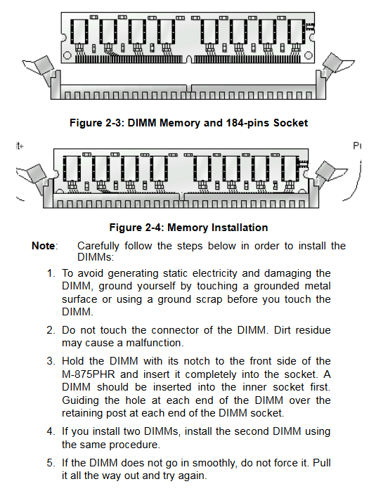
Memory: Dual 184 pin DDR DIMM slots, DDR266/333, The maximum total capacity is 2GB, with no mandatory requirement for dual channels.
Display subsystem
845GV onboard integrated graphics card, dynamic shared video memory (BIOS can set 1MB/8MB frame buffer), rear 15 pin VGA interface, no native LCD pin, only CRT output.
Internet
Onboard Intel 82562ET 10/100Mbps 100Mbps RJ45 Ethernet port, supports PXE network boot, WOL remote wake-up, and dual LED differentiation of network port speed/link status.
Storage interface
Dual channel ATA10 IDE (up to 4 IDE hard drives/optical drives)
Single 34 pin floppy drive FDC pin
No SATA interface (platform era limitation)
I/O peripheral resources
Serial port: COM1 rear DB9 fixed RS232; Onboard COM2 pin, JP1 jumper switch RS232/422/485, with terminal resistor;
Parallel port: 26 pin plug, supports SPP/EPP/ECP modes;
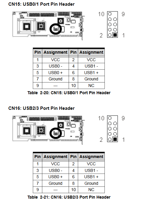
USB: 4-channel USB 2.0 onboard pins, no rear USB;
PS/2 composite keyboard and mouse rear interface;
IrDA infrared wireless communication pin;
AC97 9-pin audio expansion pin (needs to be paired with IP-ALCS20 daughter card output audio source).
Industrial specific functions
Hardware watchdog WDT (JP3 jumper control): software programmable 0-255 seconds/minute, timeout machine hardware reset, compatible with unmanned industrial control and anti freeze;
Full hardware monitoring: CPU temperature, motherboard temperature, CPU/chassis dual fan speed, Vcore/memory/3.3V/5V/12V multi-channel voltage acquisition; Can set high temperature alarm and automatic shutdown threshold;
Power supply compatible with standard ATX power supply, supporting power-off recovery, timed power on, and modem ringing wake-up;
Long life cycle industrial component selection, stable adaptation for long-term uninterrupted operation.
Machinery and Environment
Size: 13.3 “x 4.8” (338 x 122mm), weight 420g;
Working temperature range: 0-60 ℃, storage: -20~80 ℃, no condensation environment;
The overall power consumption is compatible with standard industrial ATX backplane power supply.
Hardware Installation Specification
2.1 Mandatory Requirements for CPU and Heat Sink
Socket478 ZIF installation process: Lift the pressure rod, align the CPU triangle with the socket, and lock it flat;
Hard restriction: It is prohibited to use a desktop universal downward pressure heat sink. Linghua must use a dedicated heat sink base and heat sink kit to prevent the motherboard PCB from being compressed and bent, and the circuit from breaking; During installation, tighten the screws diagonally and evenly to ensure that the CPU and heat sink are fully attached.
Installation diagram of radiator base
2.2 Memory installation
184pin DDR memory with double notch fail safe, hold the edge of the memory with both hands, press down vertically until the two end buckles automatically lock; Disassemble and open the plastic buckles on both sides, and store the idle memory in an anti-static bag.
2.3 Three core jumper functions (JP1/JP2/JP3)
Motherboard jumper layout diagram
JP1 (COM2 serial port mode): Multiple pin combinations switch RS232 (default)/RS422/RS485, which can turn on/off the bus terminal resistor;
JP2 (clear CMOS): default 1-2 short circuit works normally; Short circuit for 10 seconds 2-3 times after power failure, clear BIOS password and all parameters, and restore to factory settings;
JP3 (watchdog mode): Jumper selection timeout triggers NMI interrupt or machine hard reset.
2.4 Complete definition of full board connectors
The motherboard is divided into two categories: rear panel interface and onboard pins, all of which come with complete pin definitions:
CN1 20 pin chassis front panel: power switch, reset, power LED, hard drive indicator light, chassis speaker, keyboard lock;
CN4 ATX 4pin 12V auxiliary power supply (must be plugged in, otherwise it cannot be turned on);
CN2/CN5: Dual channel IDE; CN3 floppy drive;
CN10 CPU fan, CN9 chassis fan, 3-pin speed measurement power supply;
CN11 rear COM1, CN8 onboard COM2; CN6 parallel port;
CN13 RJ45 Ethernet port, CN17 VGA, CN19 PS/2 keyboard and mouse;
CN14 AC9 audio extension, CN12 IrDA infrared;
CN15/CN16 two sets of USB 2.0 pins.
2.5 Optional IP-ALCS20 Audio Sub Card
Accessories: Audio sub card+9-pin docking cable;
Hardware interface: CN1 3.5mm microphone/line input/line output; JP1 CD audio input; Connect the CN2 cable to the CN14 audio pin on the motherboard;
Prerequisite for use: Enable the AC97 audio controller in the BIOS and install the audio driver on the accompanying CD.
IP-ALCS20 Audio Subcard Drawing
Award BIOS Complete Setup (Press Del to enter upon startup)
The BIOS is the classic Phoenix Ward PnP firmware, with eight main menus and accompanying shortcut keys: F6 Fault Conservative Default, F7 Performance Optimal Default, F10 Save Exit, ESC Discard Modification.
3.1 Standard CMOS Features (Basic Hardware)
System time, automatic recognition of 4-channel IDE hard drives, floppy drive type, startup failure shutdown strategy, total memory viewing; You can manually customize the hard drive’s LBA/CHS mode and set the default display device to VGA.
3.2 Advanced BIOS Features
Boot sector virus protection, CPU level 1/2 cache switch, multi device boot sequence (floppy disk/hard disk/optical drive/network), NumLock boot status, graded boot password (only for setup/whole machine boot verification), APIC multi processor support, OS adaptation option with more than 64MB memory.
3.3 Advanced Chipset Features
DDR memory timing (automatically/manually adjusted by SPD), CAS delay, AGP video memory size (1/8MB optional), 15M~16M ISA memory holes, system/graphics card cache switch, PCI spread spectrum EMI suppression, CPU temperature control delay threshold.
3.4 Integrated Peripherals
IDE channel PIO/UDMA mode switch;
USB1.1/USB2.0 global switch, USB keyboard and mouse support under DOS;
AC97 audio on/off, onboard network card PXE boot ROM switch;
COM serial port address, parallel port SPP/EPP/ECP mode, infrared IR parameter configuration;
Power off and power on recovery strategy (automatic startup/keep shutdown/restore last state).
3.5 Power Management Setup
ACPI energy-saving master switch, multiple sleep modes (Doze/Standby/Suspend), hard disk scheduled sleep, CPU downshifting speed setting, network card/modem remote power on, RTC scheduled power on, long press 4-second forced shutdown settings.
3.6 PnP/PCI Configuration (Interrupt Resources)
Manually allocate IRQ/DMA channels and reserve interrupts for older ISA expansion cards; Reset the ESCD Plug and Play resource table to resolve hardware conflicts.
3.7 PC Health Status (Hardware Monitoring Panel)
Read only real-time data: CPU/motherboard temperature, dual fan speed, DC voltage of all channels on the board; Customizable CPU high temperature alarm temperature and system automatic shutdown temperature threshold.
3.8 Frequency/Voltage Control
CPU multiplier adjustment, idle PCI clock automatic shutdown, electromagnetic interference spread spectrum switch; Load default settings, password settings, and save/exit submenus together.