ADLINK NuPRO-A40H Full length PICMG1.0 Industrial Single Board Computer (SBC)
Chapter 1 Introduction: Product Core Parameters and Overall Characteristics
1. Product positioning
Standard full length PICMG1.0 industrial SHB board, LGA1155 slot, equipped with Intel H61 chipset, compatible with 3rd generation Core i7/i5/i3 and Pentium 22nm processors, aimed at high stability demand scenarios such as automation control and industrial equipment.
2. Core hardware specifications
(1) Operations and Storage
CPU: LGA1155 third-generation Core (i7-3770 3.4GHz/95W, i5-3550, i3-3220, G2120 Pentium), integrated with HD graphics and memory controller; Connect H61 PCH through DMI bus.
Chipset: Intel BD82H61 H61 Platform Controller.
Memory: 2 × 240pin DDR3 DIMMs, dual channel 1333/1600MHz, maximum 16GB; dual channel requires two memory modules with the same capacity, recommended for the same brand and specifications.
BIOS:64Mbit SPI AMI Aptio BIOS。
(2) I/O interface resources
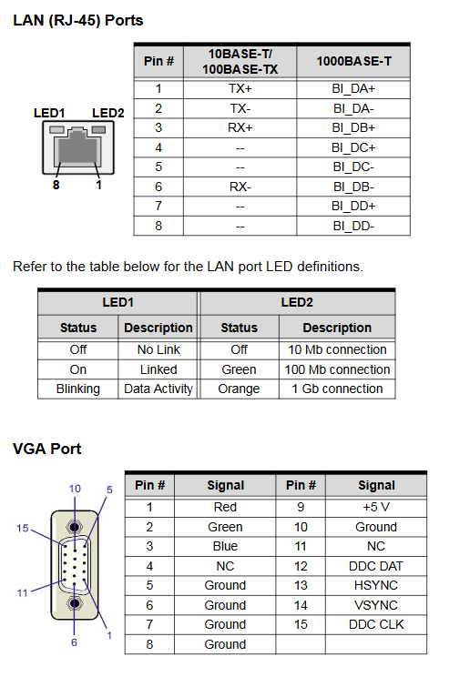
Display: VGA (rear DB15, up to 2048 x) 1536@75Hz )Onboard DVI-D pin (optional external cable connection);
Network: Dual Intel I211-AT Gigabit Ethernet ports, supporting PCIe diskless boot, WOL remote wake-up, and 9KB jumbo frames; Rear RJ45 with link/speed indicator light;
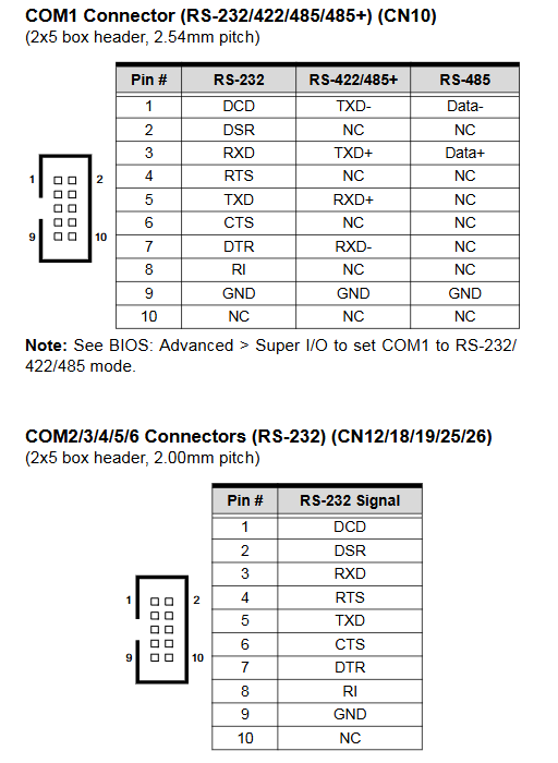
Serial COM: 6 channels in total, COM1 supports RS232/422/485 automatic flow control (BIOS+jumper switching), COM2-6 only have standard RS232; All are onboard pins, matched with DB9 baffle cables;
USB 2.0: 8-way, 2-channel rear panel, 6-way onboard pins, 480Mbps speed;
Storage: 4-channel SATA 3Gb/s high-speed hard drive interface;
Expansion bus: PCI 32bit/33MHz (ITE IT8892E bridge), ISA bus (ITE IT8888G bridge, does not support DMA);
Other: onboard parallel port LPT, PS/2 keyboard and mouse pins; Audio requires the optional DB-Audio2 daughter card to achieve HD audio;
(3) Industrial monitoring function
Watchdog WDT: 1~255 seconds/minute programmable, automatic machine reset upon timeout, can mark reset source; The onboard jumper can permanently turn off WDT;
SEMA intelligent hardware monitoring: reads CPU/motherboard temperature, fan speed, and various DC voltages, matched with SEMA Gui graphic tools and command-line tools;
Environmental parameters: size 338 × 122mm; operating temperature 0~60 ℃, storage -20~80 ℃; Humidity of 10%~90% without condensation; Certified CE and FCC Class A.
(4) Power consumption reference (i7-3770 full load test)
System idle: total power consumption of 31.49W;
CPU full load single bake: 78.41W;
Full load pressure test of the whole machine: 101.34W;
Power on surge current: total power consumption of 81.85W.
(5) Factory packaging list
Motherboard, 2 lockable SATA data cables, 2 USB dock cables, 2 different spacing COM dock cables, DVD driver, paper manual; Accessories will change with the configuration of the order.
Chapter 2 Hardware Information: Complete Definition of Onboard Interfaces and Jumpers
1. Rear panel IO (exposed interface)
Dual RJ45 Ethernet ports VGA、 2-channel USB 2.0; Detailed definition of network port 8-pin signal, VGA 15 pin RGB/Sync/DDC pins, and USB power data definition.
2. Full board connector layout and pins
The manual provides a board layout diagram, indicating all 25 onboard pins, and defining key interfaces:
CN24 ATX 12V 4Pin power supply: must be connected to provide CPU core power supply;
FAN1/FAN2 4Pin fan:+12V power supply, speed detection, speed regulation;
CN23 front panel pins: power light, power button, reset, buzzer, hard disk indicator light;
Display class: CN17 DVI-D pin, VGA rear;
Serial ports COM1~6: COM1 supports multi-mode switching and distinguishes between two pin spacing options of 2.54mm/2.0mm; DB9 baffle serial port pin correspondence table;
Peripheral pins: parallel LPT, PS/2 keyboard and mouse, 6-way USB expansion pins, 4-channel SATA hard disk ports;
Audio CN9: DB-Audio2 sub card dedicated HD audio interface;
3. Function Jumper Setting
CN14 watchdog disable jumper: 1-2 default enabled, 2-3 disable WDT;
CN28 clearing CMOS jumper: power off, short circuit 2-3 to clear BIOS settings;
CN29 clearing RTC jumper: clearing BIOS+system time;
COM1 mode jumper CN16/CN31: Combination switch RS232/422/485 working mode.
Chapter 3 Getting Started: Hardware Installation Step by Step Tutorial
Security prerequisite requirements
Disconnect the power supply throughout the entire process, wear an anti-static wristband, and operate on an anti-static workbench. Do not touch the socket contacts to prevent static electricity from burning components.
1. CPU installation (LGA1155 slot)
Release the slot lock rod, lift the load pressure plate, and remove the protective cover;
Align the CPU triangle mark with the Pin1 positioning angle of the slot and insert it in one direction. It is strictly prohibited to press it forcefully;
Lower the pressure plate and fasten the locking rod to fix the CPU.
2. Installation of CPU heatsink and fan
Apply thermal grease evenly on the surface of the CPU;
Fixed radiator, fan power cord connected to FAN1;
Mandatory requirement: Cooling must be installed, otherwise the CPU/motherboard will be permanently damaged; The maximum temperature limit for the chassis environment is 50 ℃.
3. DDR3 memory installation
Open the DIMM slot buckle, align the memory gap with the slot partition;
Press the memory vertically until the buckle automatically rebounds and locks;
Dual channel rule: DIMM1 and DIMM2 have exactly the same capacity, and it is recommended to use the same model of memory.
4. Key points of power wiring
CN24 ATX12V 4Pin must be connected, and both AT/ATX power supply modes rely on this power supply; Linghua adapter cables can be purchased without matching wires;
The front panel CN23 must be connected to the power on and ATX standby signals, otherwise it cannot be powered on.
Chapter 4 Driver Installation: Windows Driver Installation Guide
Compatible Systems
Windows XP 32/64 bit, Win7, Fedora17, RedHat Enterprise Linux; The driver is stored in the corresponding directory of the accompanying DVD.
Driver installation sequence
Intel chipset INF driver;
. Net Framework 3.5 (kernel driver pre dependency);
Intel HD integrated graphics card driver;
Intel I211 dual network card driver;
Optional DB-Audio2 sub card HD audio driver (BIOS requires Azalia audio to be enabled first);
After each installation step is completed, restart the system according to the prompts.
Chapter 5 BIOS Setup: Detailed Explanation of AMI Aptio Full Menu Configuration
1. Enter BIOS mode
Press the Delete key to enter during power on self-test, and press F7 to bring up the quick selection menu for startup options; Full interface shortcut keys: F1 Help, F3 Load Optimization Default, F10 Save Exit, ESC Discard Changes.
2. Complete functions of the seven main menus
(1) Main Page
Display BIOS version, overall memory, system time/date, and administrator permission level; The system clock can be modified.
(2) Advanced Settings (Core Industrial Control Configuration)
ACPI settings: sleep mode S1, AT/ATX power shutdown logic;
CPU configuration: number of cores turned on, VT virtualization, XD protection, EIST energy-saving, Turbo frequency switch;
SATA configuration: Switch IDE/AHCI/RAID hard disk mode;
USB configuration: Legacy USB support (DOS/BIOS keyboard and mouse available);
Super IO: 6-way serial port, parallel port enabled/disabled, IO address/IRQ allocation, COM1 communication mode;
Serial console redirection: COM1-6 remote terminal parameters (baud rate 115200, VT100 terminal, etc.), supporting server remote out of band management EMS;
CPU PPM power management: energy-saving C3/C6/C7 sleep switch.
(3) Chipset chipset settings
PCH IO: high-precision timer, power-off recovery power on logic (power on/keep off/last state), built-in audio Azalia switch;
System Agent graphics card/memory: DVMT allocation of core graphics memory, selection of main display device, remapping switch for memory above 4G.
(4) Boot startup menu
Startup timeout, NumLock startup, Logo silent startup, Fast Boot quick startup;
Priority of device startup, CSM compatibility mode (UEFI/Legacy boot switch), and ROM strategy for PCIe network card boot.
(5) Security Menu
Two level password: administrator password (restricted to BIOS access only), user boot password (boot+BIOS double check); Forgot password requires CMOS reset.
(6) System Management
SEMA monitoring data: total operating time, power on times, real-time temperature of CPU/motherboard, and voltage of each channel; Power on watchdog Power Up WDT switch.
(7) Save&Exit Exit menu
Save/discard modifications, restart, restore factory default, single temporary device startup, and other functions.
Appendix A: Watchdog WDT Function
Function: The software sets a timeout of 1-255 seconds/minute, and if there is no feeding to the dog, the entire machine will be reset hard; Register mark reset is triggered by WDT, and the system can read and determine the cause of the fault upon startup;
Usage: Download the SEMA driver from the official website and place it in the system driver directory. Provide C language example code to implement WDT activation, timeout configuration, and dog feeding operations.
Appendix B: Mapping of System Bottom Hardware Resources (Essential for Industrial Control Development)
Provide complete hardware address allocation at the bottom of the board for driver and upper computer IO development:
B. 1. System memory mapping: BIOS, ISA holes, VRAM, APIC interrupt memory address segments;
B. 2 DMA channel allocation: parallel port, floppy disk occupied channels, list of available channels;
B. 3 IO port address table: serial port, parallel port, VGA, PCI configuration SMBus、 Hardware monitoring of all IO base addresses;
B. 4/B.5 IRQ Interrupt Table: Two types of interrupt allocation: PIC Traditional Mode and APIC Advanced Mode, distinguishing between onboard devices and idle PCI interrupts;
B. 6 PCI device topology: bus/device/function number, including bridge, dual network card, SATA, USB controller;
B. 7 PCI interrupt routing table: INT interrupt lines corresponding to each onboard PCI device.
Important safety regulations
Power off and disconnect the power cord before operation, stay away from liquids and high temperatures, and ensure ventilation;
Do not disassemble and repair on your own, only authorize engineers to maintain;
The motherboard is equipped with lithium batteries, and there is a risk of explosion if the model is replaced incorrectly. The waste batteries are collected in compliance with regulations;
Stop using immediately in case of power cord damage, water ingress, or physical impact. Contact after-sales service.