ADLINK NuPRO-E315 Full length PICMG 1.3 Industrial SHB Single Board Computer
Chapter 1 Product Overview and Hardware Specifications
Version and Platform Positioning
Standard full length PICMG 1.3 SHB, size 338 × 126mm; LGA775 single channel platform, Intel G41+ICH7R chipset, designed for automation, machine vision, testing and measurement industrial control scenarios, with native support for PCIe x16 independent graphics card expansion.
Core computing hardware
CPU: LGA775 slot, supports Conroe/Wolfdale/Yorkshire series Core 2 quad/dual core, Pentium, Celeron; FSB 800/1066/1333MHz, Main frequency up to 3.0GHz
Chipset: G41 GMCH integrated GMA X4500 graphics card+ICH7R southbridge, supporting RAID0/1/5/10 arrays
Memory: Dual channel 240pin DDR3 DIMM x 2800/1066MHz, maximum 4GB; dual channel requires two memory modules of the same capacity and specifications
BIOS:32Mbit SPI AMI BIOS, Support PXE, serial remote console, BIOS refresh, and graded boot password
Full board I/O resource list
Display
Rear DB15 VGA interface, up to 2048 x 1536@75Hz , GMA X4500 integrated graphics card supports DX10 and OpenGL 2.0
Internet
Single Intel 82574L PCIe x1 Gigabit RJ45 Ethernet port, rear panel, supports PXE diskless, WOL remote wake-up, and jumbo frames; Dual color indicator lights on the Ethernet port distinguish between speed and link status
Serial port (6 channels in total)
COM1 (rear DB9): Supports RS232/422/485/485+four modes, JP1-JP4 jumper switching levels
COM2~6 (onboard pins): Standard RS232, independent IO address and IRQ
storage
4-way onboard SATA 3Gb/s interface, ICH7R supports Intel RST disk array
USB 2.0 (8 channels in total)
4-channel onboard pins+4-channel led out through backplane gold fingers, single port 5V/0.5A with overcurrent protection
Traditional Industrial IO
26 pin pin IEEE1284 parallel port, BIOS switches to Normal/EPP/ECP mode
Rear Mini DIN composite PS/2 keyboard and mouse interface (with accompanying Y cable for keyboard and mouse connection)
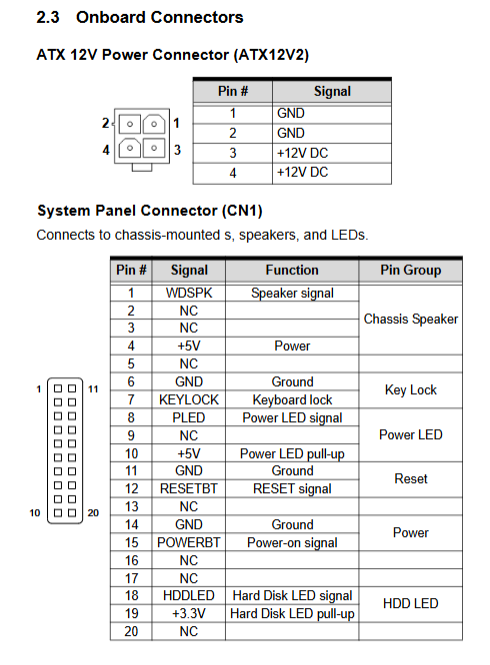
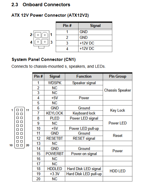
Front panel pins: power on, reset, power light, hard disk light, buzzer
Expansion bus (backplane gold finger lead out)
PCIe x16 (discrete graphics), PCIe x4, 32bit/33MHz PCI bus
audio
Onboard HD Audio pin, DB-Audio2 daughter card must be selected to output audio
Hardware monitoring and watchdog
W83627DHG SuperIO chip: real-time acquisition of CPU/motherboard temperature, dual fan speed, and various DC voltages;
Programmable WDT: 1~255 seconds/1~255 minutes dual gear, timeout machine hard reset, register mark WDT triggers restart for fault tracing
Power consumption measurement (complete data for multiple CPUs)
Test power supply FSP460-60PFG, paired with 2 x 2GB DDR3+160GB SATA hard drive:
Q9400 quad core: DOS standby 46.32W, full load machine 75.70W
E8400 dual core: DOS standby 50.57W, full load 65.30W
E7400 dual core: DOS standby 39.84W, full load 54.75W
E6400 dual core: DOS standby 42.62W, full load 55.07W
E5300 Pentium: DOS standby 37.10W, full load 50.60W
Environmental Parameters
Working temperature 0~60 ℃ (forced air duct heat dissipation), storage -20~80 ℃; Humidity 10%~90%, no condensation
Chapter 2: Complete Definition of Hardware Connectors and Jumpers
2.1 Rear exposed panel IO (from top to bottom)
PS/2 composite port DB15 VGA、 Gigabit RJ45 Ethernet port DB9 COM1; The document provides a complete list of pin definitions and indicator logic for each type of interface.
2.2 All onboard connectors
ATX12V 4Pin CPU auxiliary power supply (must be plugged in, otherwise it cannot be turned on)
CPUFAN/SYSFAN dual 4pin fan socket (speed measurement+PWM speed regulation)
DIMM1/DIMM2 DDR3 memory slots
SATA1~4 storage interface, 26 pin parallel LPT
USB dual row plug, COM2-6 serial port plug
HDAUD1 audio daughter card dedicated pin, SPI debugging pin
CN1 front panel 20 pin pins (power on/off, LED, buzzer)
KBMS2 external keyboard pin, GPIO universal IO pin
2.3 Core Function Jumper
JBAT1 Clear CMOS: Power off, short circuit 2-3 pins to clear BIOS settings, system time, and boot password
PSON1 AT/ATX power mode switching: 1-2=AT constant power supply, 2-3=standard ATX on/off mode
JP1~JP4 COM1 level combination jumper: Multiple jumpers paired to switch RS232/422/485/485+four bus modes
Chapter 3 Hardware Step by Step Installation Guide (Mandatory Anti static Requirements)
Full process anti-static workbench+grounding wristband. Do not touch the slot contacts as static electricity can permanently damage the hardware.
LGA775 CPU Installation
Press down the slot lock rod, lift up the load pressure plate, and remove the plastic protective cover
Align the golden triangle mark of the CPU with the bottom left corner of the slot, and place it flat without violent pressing
Close the pressure plate and fasten the locking rod to fix the CPU
Installation of radiator
Provide 3 officially recommended LGA775 heat dissipation models (1U thin/3U standard/copper core high-performance); Installation points:
The back of the motherboard is fixed with a backplate, and the bottom of the heat dissipation is evenly coated with thermal conductive silicone grease
Diagonal step-by-step locking screws to avoid uneven stress and bending of PCB
Connect the fan power cord to the CPUFAN socket; It is strictly prohibited to start the computer without heat dissipation and burn out the CPU
DDR3 Memory Installation
Open the buckles on both sides of the slot, align the memory gap with the partition, and press down vertically. The buckles will automatically rebound and lock in place; Two channels must have the same capacity, while a single channel only experiences a decrease in performance.
Chapter 4 Driver Installation (Windows XP/7)
Unified storage of supporting CDs for drivers, fixed installation sequence, system restart completed at each step:
Intel RST Fast Storage Driver: When installing the XP system, load the F6 floppy disk and enable AHCI/RAID; Win7 does not require preloading
G41 chipset INF bus driver, recognizes all PCIe/PCI hardware
GMA X4500 integrated graphics card driver, supports multi-resolution and video hardware decoding
82574L Gigabit Ethernet card driver, enabling PXE/WOL functionality
HD Audio Driver: Only compatible with DB-Audio2 daughter card, BIOS requires pre activation of audio controller
Chapter 5: Detailed Explanation of AMI BIOS Complete Setup Menu
Press Del to enter BIOS during power on self-test, F1 help, F10 save exit, ESC abandon modification, configure eight main menus item by item:
5.1 Main Page
Display CPU model, memory capacity, BIOS version, system time/date, basic clock modification
5.2 Advanced Settings (Industrial Control Core Configuration)
CPU configuration: VT virtualization, C1E energy-saving, multi-core switch, CPU temperature protection
IDE/SATA configuration: SATA switches IDE/AHCI/RAID mode, automatic recognition of hard disk parameters
Super IO configuration: 6-way serial port address/IRQ allocation, parallel port mode, WDT second/minute gear switch
Hardware health: CPU intelligent fan (with three levels of temperature control: silent/balanced/performance), real-time voltage and temperature display
Remote console: COM1 serial port redirection, supports debugging BIOS/system without display
APM power management: power-off recovery logic, RTC timed power on, network card wake-up
5.3 PCI/PnP Settings
IRQ/DRM resource manual reservation (compatible with old ISA devices), PCI delay timer, plug and play system switch
5.4 Boot Start Menu
Priority of device startup, Quick Boot self-test, NumLock status during startup, PCIe network card boot switch
5.5 Security Menu
Administrator/user two-level startup password, password forgotten requires clear CMOS reset
5.6 Chipset Chipset Settings
North Bridge: DDR3 frequency, memory remapping, integrated graphics card memory allocation, main graphics card selection (PCIe discrete graphics/onboard VGA)
Nanqiao: USB port quantity switch, Legacy USB DOS support, network card ROM, audio controller switch
5.7 Exit Exit menu
Save/abandon restart, load optimal/fail safe default BIOS parameters
Appendix A: Watchdog WDT Development Materials
Hardware based on W83627DHG SuperIO, controlled through 0x2E/0x2F standard SuperIO ports
Operation process: Unlock SuperIO → Select WDT logical device → Enable timer → Set timer duration → Feed dog regularly
Provide complete C language low-level register operation example code, which can be directly ported to DOS/Windows industrial control programs
Reading the register after restarting can determine whether the current shutdown is caused by a watchdog timeout
Appendix B: Mapping of System Bottom Hardware Resources (Essential for Industrial Control Development)
Complete standardized table:
System Memory Address Allocation Table
DMA channel occupancy list
Hexadecimal addresses of IO ports for all onboard devices
APIC Advanced Interrupt IRQ Allocation Table
PCI/PCIe bus device topology (bus/device/function number)
PCI interrupt routing mapping table, used for the development of underlying drivers for sports cards and acquisition cards
Safety operation standards
Before disassembly, completely disconnect the power supply, stay away from liquids and high temperatures, and ensure ventilation of the chassis
Mainboard CR2032 lithium battery, there is a risk of explosion if the model is replaced incorrectly, and the waste battery is recycled in compliance with regulations
Private disassembly, water ingress, mismatched power supply, physical impact, and electrostatic damage are not covered by the warranty
The use of snap fasteners for fixing radiators is prohibited as it may compress the PCB and cause circuit breakage