ADLINK ACL-8112 series multifunctional ISA acquisition card
Product series models and core positioning
ACL-8112 is an ISA bus integrated multifunctional DAQ, which integrates analog input AI, analog output AO, 16 DI/DO, 8254 timing counter, and three models with differentiated gain and channel configurations:
Model AI Channel Configuration Programmable Gain Core Applicable Scenarios
ACL-8112HG 16 Single End/8-Differential Ultra High Gain: 0.5/1/5/10/50/100/500/1000 Millivolt Weak Signal (Thermocouple, Micro Sensor)
ACL-8112DG 16 single ended/8 differential standard gain: 0.5/1/2/4/8 times universal industrial voltage acquisition
ACL-8112PG is only 16 single ended, without differential 1/2/4/8/16 times, hardware jumper switching ± 5/± 10V range, low-cost standard voltage acquisition
Core universal hardware functions
AI: 12 bit successive approximation ADC, single channel conversion of 8 μ s, up to 100kS/s sampling;
AO: 2-channel 12 bit double buffer multiplication DAC, outputting 0~5V/0~10V;
DIO: 16 TTL inputs+16 TTL outputs;
Timing: onboard 8254, 3-channel 16 bit counter, 2MHz reference, 2-channel cascaded sampling clock, 1-channel user free use;
Transmission support: three AD data transfer modes: software polling, hardware interrupt, and DMA.
Typical Applications
Industrial equipment switch control, energy monitoring, alarm system, product function testing, pulse/frequency measurement, waveform signal generation, BCD peripheral driver.
Complete hardware and electrical specifications
1 Analog Input (A/D)
Resolution: 12 bits; Input impedance 10M Ω; ± 35V continuous overvoltage protection;
HG range: single/bipolar, minimum ± 5mV high gain range;
DG range: ± 10V~± 0.625V, unipolar 0~10V series;
PG range: hardware JP9 switches to ± 5V or ± 10V basic mode, software switches to 5 gain modes;
Accuracy: Low gain 0.01% FS ± 1LSB, ultra-high gain up to 0.04% FS;
Trigger methods: software trigger, internal timer trigger, external edge trigger;
Data transmission: polling/interrupt/DMA; FIFO none, real-time register read.
2 Analog outputs (D/A)
2-channel 12 bit dual buffer DAC, linear error ± 0.5LSB; Establishment time 30 μ s;
Drive capability ± 5mA; reference source optional onboard -5V/-10V or external precision reference;
Output formula: Vout=- VRef × (DA value/4096);
Double buffering mechanism: Write the lower 8 bits first, then the higher 4 bits, and output a one-time refresh without any step transitions.
3-digit IO (DIO)
16 in 16 out, standard TTL level;
Input low ≤ 0.8V, high ≥ 2.0V; maximum output current of 8mA, pulling current of 0.4mA;
Independent 20 pin CN1 (DO), CN2 (DI) terminals, 37 pin CN3 integrated analog and counting signals.
4 8254 Timer Counter
Counter 1+2 cascaded to generate AD sampling clock (0.00046Hz~100kHz);
Counter 0 is open to users for measuring frequency, pulse PWM、 Single trigger;
The clock source can be either onboard 2MHz or external CN3 ExtCLK.
5 General Machinery/Electrical
Bus: Old ISA AT bus; Half length PCB;
The I/O address occupies 16 consecutive ports (default 0x220, 0x200~0x3FF adjustable);
Interrupt IRQ options 3/5/6/7/9/10/11/12/15; DMA supports 1/3 channel;
Power supply:+5V 430~450mA,+12V 150mA;
Temperature range: working at 0-55 ℃, storage at -20~80 ℃, no condensation at 5-95% humidity.
Hardware jumper, dialing and installation configuration
1 Core DIP SW1 (6-digit DIP)
Set the base address of the board card, default to 0x220 at the factory, covering all valid ISA addresses from 0x200 to 0x3FF.
2 Key jumper functions
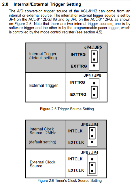
JP3 (DG/HG): Single ended/differential AI mode switching; PG does not have this jumper, only single ended;
JP4/JP5: AD trigger source (internal timing/external ExtTrig);
JP6/JP4: 8254 counter 0 clock (internal 2MHz/external CN3 clock);
JP5/JP3: IRQ interrupt channel selection, supports 9-level interrupts, can turn off interrupts;
JP7/JP8: DMA channel 1/3 selection, recommended DMA3 for floppy disk drives and DMA1 for hard disk drives;
JP1/JP8: DAC internal reference -5V/-10V switching;
JP2/JP6/JP7: Two channels of DAC independently select internal/external reference voltage;
JP9 (PG only): Global AI maximum range ± 5V/± 10V switching.
3 Installation specifications
Anti static operation, anti-static pad/wristband;
Turn off the power and disassemble the device. Adjust the jumper and insert it into the idle ISA slot to lock it;
Multi card limit: up to 2 ACL-8112 cards, only supports DMA1 and DMA3 channels, and cannot share IRQ with multiple cards;
4 matching terminal boards
5 specialized adapter boards:
ACLD-8125: Thermocouple cold end compensation, suitable for HG high gain temperature measurement;
ACLD-9137: Standard 37 pin screw terminal;
ACLD-9182:16 channel isolation DI board;
ACLD-9185:16 relay DO output;
ACLD-9188: Universal 37 pin DIN terminal board.
Connector Pin and Wiring Specification
Three sets of external interfaces for the board:
CN1 (20 pin): 16 digital outputs DO,+5V/+12V, digital ground;
CN2 (20 pin): 16 digital input DI, power supply, digital ground;
CN3 (37 pin D-Sub rear main interface):
AI single ended: AI0~AI15 analog input;
Differential AI (DG/HG): AIH+/AIL – paired channels;
AO0/AO1 two analog outputs;
ExtRef external reference, ExtTrig external trigger, ExtCLK external counting clock;
8254 Counter0 GATE/OUT signal;
Independently simulate AGND and digitally simulate DGND.
Selection rules for signal wiring
Floating sensor (ungrounded): single ended input;
On site grounding signal source: differential input suppresses ground loop noise;
Differential sensors (such as strain gauges): forced differential mode.
Complete manual for low-level registers
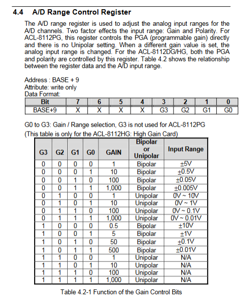
The board occupies 16 I/O ports from BASE to BASE+15, and the read and write functions and bit definitions of each register are fully listed
BASE+0~3:8254 counter read/write, control word;
BASE+4/5: AD conversion of 12 bit data (low byte/high byte, DRDY ready flag);
BASE+6/7:16 DI high and low byte read-only;
BASE+4~7 are simultaneously used as two DACs to write into registers;
BASE+9: AD gain/polarity control register;
BASE+10: Multiplexing channel selection register;
BASE+11: AD working mode register (trigger+transfer mode);
BASE+12: Software trigger register;
BASE+13/14:16 path DO only writes high and low bytes;
BASE+8: Interrupt clearing register.
The complete bit table covers gain encoding, channel selection, trigger mode, and interrupt flags, making it suitable for bare metal programming without libraries.
Hardware working principle
1. A/D acquisition process
Select the AI channel in the channel register, and the PGA will automatically switch gain;
Three types of triggers: software write register trigger, 8254 timing pulse, external CN3 edge;
Set DRDY flag upon completion of conversion; Three reading methods:
Polling: cyclically read DRDY bits to determine data readiness;
Interrupt: After the conversion is completed, an ISA interrupt is sent and ISR reads the data;
DMA: Directly transfer data to memory without occupying CPU;
2 D/A output logic
A double buffered 12 bit register must be written to the low byte first and then the high byte to avoid intermediate erroneous voltage output; Support free switching between internal and external benchmarks to adapt to precision signal sources.
3 8254 Counter Architecture
Counter1+2 cascade: Frequency division generates uniform AD sampling pulses;
Counter0 independent: Gate control, clock, and output are all exported to CN3, supporting 6 counting modes (single, square wave, event counting, etc.).
Whole machine calibration process
The board is equipped with 6 adjustable precision potentiometers VR, which are used to offset zero point, full range, and operational amplifier offset errors:
VR1: AD full-scale, VR2: bipolar zero, VR6: unipolar zero;
VR5: PGA operational amplifier offset, VR3/VR4: two DAC full range;
Calibration tool requirements
Five and a half high-precision multimeter, standard DC voltage source, and matching 8112fil calibration software;
Steps
Preheat for 15 minutes;
DAC full-scale calibration;
PGA operational amplifier zero calibration;
AD bipolar zero/full-scale calibration;
AD unipolar supplementary calibration (DG/HG only);
Calibration parameters are not lost during power outages, ensuring long-term acquisition accuracy.
DOS C development function library
Provide a complete set of 23 standardized C APIs, distinguishing HG/DG/PG models, and supporting 8 complete demo source codes:
Core Universal Functions
_8111_Initial: board initialization, must be called first;
_811_2AD_Set_Channel: Select the analog input channel;
_811_2AD_Set_Sange: Software settings for gain range;
_811_2AD_Set_Sode: Configure trigger+DMA/interrupt transfer;
_8112-AD_Soft_Trig: software single acquisition;
_811_2AD_Squire: Read AD conversion values;
_811_2DA: Set two analog output voltages;
_8112dI/_8112dO: Digital IO read and write;
_8111_TIMER_Start/Read: 8254 counter configuration read;
DMA/interrupt set functions: AD_SMA_Start/Stop, AD-IN_Start/Stop;
Demo Program Checklist
AD single acquisition, interrupt acquisition, DMA high-speed acquisition, multi-channel scanning, DA waveform output, DI digital reading, DO switch control, counter frequency measurement, can be directly compiled and run.