ADLINK SP-15W03 15.6-inch intelligent all-in-one machine
Product Introduction: Core Parameters of Hardware Platform
Whole machine positioning
Highly integrated industrial touch panel, onboard CPU motherboard+15.6-inch 16:9 LCD, designed for device integrators to quickly customize industrial control terminals, significantly reducing overall development workload.
Core hardware architecture diagram
CPU: Intel Atom D525 dual core 1.8GHz, 1MB L2 cache
Chipset: Intel ICH8M
Graphics card: NVIDIA ION2 GT218, onboard 512MB GDDR3 discrete graphics memory
Memory: Single DDR3 SO-DIMM slot, maximum 2GB@800MT /s
Storage: onboard 7+9-pin SATA socket, supporting 1.8-inch HDD/SSD; SATA signal can be exported to external I/O port for external hard disk connection
Expansion: Two Mini PCIe full height slots, one of which comes with a SIM card slot (4G/wireless communication expansion)
Display: Dual channel 24 bit LVDS driver with built-in 15.6-inch screen and VGA/DVI/DP external display output
Peripherals: Dual Gigabit Ethernet, Dual RS232 Serial Port, 6-way USB 2.0, Audio, 4-way GPIO, 5-wire Resistive Touch Screen Controller
Complete specification parameters
(1) Display section
Screen: 15.6-inch 16:9 transmissive LED backlight TFT
Resolution: 1920 × 1080
Typical brightness of 300cd/m ² (no touch), contrast ratio of 400:1
Optional accessories: 5-wire resistive touch screen (onboard USB touch controller)
(2) Processor&Storage
CPU: Atom D525 dual core 1.8GB; maximum memory 2GB DDR3; Exclusive GT218 512MB VRAM
Storage: Built in 1.8-inch SATA hard drive slot, external I/O leads out SATA signal for expandable storage
(3) I/O interface resources
Network port: 2 × 10/100/1000Mbps Gigabit Ethernet
Serial port: 2-channel RS232 (COM1/COM2)
USB: 6-way USB 2.0 high-speed
Video output: VGA (CRT), DVI, DisplayPort, built-in LVDS
Audio: microphone input, line output, stereo speaker amplifier output
General IO: 4-channel GPIO, power button, reset button, hard disk/network port status indicator light
(4) Power supply specifications
Standard DC input: 19VDC (± 15%)
Optional backup lithium battery: 3S2P 11.1V 5200mAh, with a maximum backup battery life of 2 hours in case of power failure
Onboard DC OUT socket: External output+5V, 3.3V, standby 5VSB/3.3VSB power supply
(5) Environment and Certification
Working temperature: 0 ℃~60 ℃; Storage temperature: -20 ℃~60 ℃
Humidity: 0~90% without condensation at 40 ℃
Certification: CE, FCC Class A/B
Standard unboxing list
1 SP-15W03 complete machine, 1 device driver CD
Detailed description of system hardware (core hardware information)
Mechanical dimensions
Provide a two-dimensional engineering drawing of the entire machine, indicating the length, width, thickness, and installation hole specifications (4 × φ 3.2 installation holes), and provide the overall tolerance dimensions of the machine.
Four sets of 30 pin I/O connectors (SMP-IOA/IOB/IOC/IOD) for external motherboard
There are 4 board to board sockets on the side of the motherboard, and all peripheral signals are led out from these 4 sets of terminals. The external IO adapter board can be customized:
SMP-IOA:USB2~USB5、 Second Gigabit Ethernet GBE2, external SATA, hard disk indicator light, SMBUS bus
SMP-IOB: Stereo speaker amplifier, power/reset button COM1、USB0/USB1、 The first gigabit network GBE1
SMP-IOC: DVI video, DisplayPort (DP) display differential signal, 3.3V display power supply
SMP-IOD: Audio Input/Output, VGA (CRT) Red Green Blue Sync Signal COM2、 4-channel GPIO (GPO1~GPO4)
Each connector comes with a complete pin definition table and external dimension drawing.
Power specific connectors (DC IN/DC OUT/Battery)
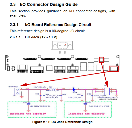
DC IN: 6Pin, 19V main power input, multiple 19V parallel connections with GND
DC OUT:10Pin, External output of 3.3V, 5V, 3.3VSB, 5VSB, and multiple GND to power peripherals
Battery: 12 pin lithium battery socket, including battery power, temperature detection, SMBUS communication pins
External I/O reference circuit design (for use as an adapter board by integrators)
The document provides a complete set of peripheral standard reference schematics, including:
DC power input, USB 2.0 dual port, dual Gigabit Ethernet port, dual RS232 serial port DP、DVI、VGA、 Microphone/line audio; All circuits come standard with ESD protection, magnetic bead filtering, and large capacity filtering capacitors to meet the anti-interference requirements of industrial control.
Onboard internal slots (pluggable components on the back of the motherboard)
DDR3 SODIMM memory slot: angled installation, maximum 2GB
1.8-inch SATA hard drive holder: direct insertion SSD/HDD interface
Mini PCIe 1: Full height, USB/PCIe signal, paired with SIM card holder (4G module specific)
Mini PCIe 2: Full height, USB/PCIe (WiFi/Bluetooth extension)
Fan 4pin socket:+5V power supply, speed detection, speed control pin
Specification for supporting cables
Provide complete cable design for IOA/IOB/IOC/OD, DC IN, and DC OUT: wire sequence comparison table, wire specifications (UL1571 28AWG/UL1007 24AWG), impedance withstand voltage, material list, wire color definition, label specifications, all in compliance with RoHS environmental standards.
Chassis, heat dissipation EMC、 Complete Machine Installation Design Guide (for System integrators)
Considerations for chassis design
Coverage of usage scenarios: indoor/outdoor, temperature and humidity, impact and vibration, dust and water resistance, corrosion resistance, UV exposure, explosion-proof, sterile medical and other multi scenario design constraints.
Thermal Design Specification
Active heat dissipation: fan selection, fan socket speed regulation function, air duct planning
Fanless passive heat dissipation: CPU/GPU thermal conductivity structure, heat dissipation pad/metal heat sink contact requirements, reduce thermal resistance
Chip power consumption evaluation: Reference to Intel/NVIDIA original factory thermal design parameters for overall heat dissipation margin
EMI Electromagnetic Compatibility and Safety Design
EMI suppression: Add filtering devices to the IO interface, fully overlap the IO baffle with the chassis shell, ground the metal frame of the front screen, and shield the high-speed differential cable; Can apply for Linghua FAE paid design consulting
EMS anti-interference: power filtering, large capacity buffer capacitor, complete grounding path
Product safety: certified power supply, fire-resistant cables, no sharp edges, high voltage rapid release, environmentally friendly recycling compliance
IO Structure and Whole Machine Assembly Specification
IO opening: Ensure continuous metal shielding, shorten cables as much as possible, make fixed buckles, and use waterproof connectors for outdoor use
Screen installation: The installation bracket should not cause twisting/bending stress on the touch screen, and the back panel should be evenly supported to avoid LCD damage from stress
Whole machine selection: Choose the shell material, surface treatment, ventilation holes, installation method, light transmission brightness, and touch fit process according to the environment; Public areas require anti damage structures and can be customized with IP protection levels
AMIBIOS 8 setup and driver installation
BIOS entry method
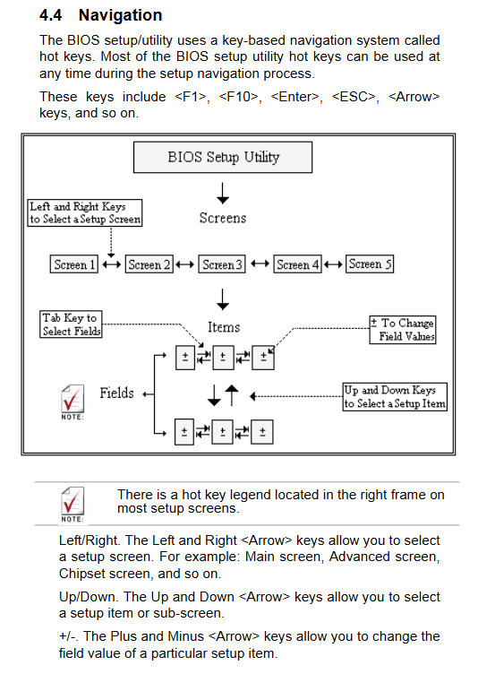
Press the Delete key during power on self-test to enter the settings interface, which supports F1 help, F10 save exit, ESC abandon modification, F8 load fault default, F9 load optimal performance default.
BIOS complete menu module
Main: Overview of System Time, Memory, and Hardware
Advanced (Core Configuration)
CPU settings: Hyper threading, SpeedStep energy-saving, C-State sleep, XD protection bit
IDE/SATA settings: AHCI/RAID/compatibility mode, hard drive S.M.A.R.T, PIO/DMA mode
Super IO: Dual serial port address/interrupt, power on/off recovery strategy (power on/off/hold)
Hardware monitoring: CPU temperature, various voltages, fan speed regulation, LCD brightness adjustment
ACPI power supply: S1/S3 sleep, USB wake-up, HPET high-precision timer
PCIe、MPS、SMBIOS、 Remote serial port console, USB global configuration
PCI PnP: IRQ/DMA resource allocation, plug and play system settings
Boot: boot sequence, quick boot, network boot, NumLock power on status
Security: administrator/user two-level boot password setting, password clearing
Chipset: North South Bridge memory timing, graphics card initialization, USB/audio bus switch
Exit: Save/discard modifications, load factory default parameters
Driver installation path
The driver CD contains a complete set of XP and Win7 32/64 bit drivers, including chipset, NVIDIA graphics card, sound card, dual network card, touch screen drivers, and the installation paths for each system are marked in the documentation.
Safety operation instructions
The power must be cut off before installation/maintenance; Equipment should be kept away from liquids, high temperatures, and enclosed environments without ventilation
Only the original factory compatible power supply is used, and the power cord should be protected from compression and damage; Long term idle power outage
Replacing the wrong model of built-in lithium battery poses a risk of explosion, and waste batteries should be recycled according to regulations
Only authorized engineers are authorized to repair the malfunction. In case of water ingress, falling, or wire damage, the power should be immediately cut off and sent for repair