ADLINK MXE ‑ 230 series ultra compact fanless
Product Introduction
Product Positioning
MXE-230 all aluminum alloy fanless industrial computer, based on Intel Alder Lake-N/Amston Lake N97 processors; Targeting industrial automation and edge collection; Modular SKU, expandable with multiple serial ports, multiple network ports, and isolated DI/DO; Supports Wi Fi, 4G LTE, NVMe SSD expansion; Resistance to impact 30G, vibration 3Grms.
Packing List
Standard configuration: MXE-230 host, wall bracket, DIN rail/storage screw kit, quick start guide
Optional accessories: 120W AC-DC power adapter (part number 31-62163-1000-A0)
Overview of Core Hardware
CPU:Intel Alder Lake‑N N97
Memory: DDR5-4800 SO-DIMM, maximum 16GB
Display: HDMI+DP1.2, supports 4K@60Hz
Network: Basic version 2-channel Intel I210IT Gigabit Network; SKU variant MXE-231/4LAN is a 4-port version
Serial port: Basic 2-channel DB-9, BIOS switch RS232/422/485;
MXE-231/4COM: 4-channel serial port, with 2 channels isolated at 2.5kV; Comes with 8DI+8DO 2.5kV isolated digital IO
MXE-231/6COM: 6 serial ports, including 4 isolated 2.5kV channels; Comes with 8DI+8DO 2.5kV isolated digital IO
USB: 1 x USB 3.0 Gen2 (output 1A)+3 x USB 2.0
Storage Expansion
M.2 M‑Key(2280,PCIe Gen3 x2,NVMe SSD)
M. 2B Key (3042, USB bus only, for 4G/LTE module, with Micro SIM)
M. 2 E-Key (2230, Wi Fi/Bluetooth)
Onboard SATA 6Gb/s, compatible with 2.5-inch SSD
Audio: Realtek ALC888S HD audio; Onboard 40pin pin pin lead out Line in, Line out, MIC in
Safety: TPM2.0
Power supply: 12-24V DC input
Mechanical Dimensions
Basic version: 165 (W) × 120 (D) × 62 (H) mm
4COM/6COM/4LAN variant height 75mm
environmental parameters
Working temperature: -20~+60 ℃; Storage -40~85 ℃
Humidity: Operating at 10-85% non condensing; Store 10-95% non condensing
Anti vibration 3Grms; Impact resistance 30G
Operating system support: Windows 10 IoT Enterprise LTSC21H2 64 bit, Ubuntu 22.04
Power consumption reference
Mode power consumption description
Shutdown 3.9W DC, keyboard and mouse only
System idle 12.3W Windows desktop idle
CPU full load 30.1W CPU+graphics 100% load
The whole machine is fully loaded with 30.3W CPU and all I/O working simultaneously
Recommended power supply ≥ 40W, consideration for high temperature environment derating
SKU version differentiation table
Model SKU Network Port Serial Port Isolation DIO Machine Height
MXE-231 Standard Edition 2 × GbE 2-channel (non isolated) without 62mm
MXE-231/4LAN 4 × GbE 2-channel without 75mm
MXE-231/4COM 2 × GbE 4COM (2-channel 2.5kV isolation) 8DI/8DO 2.5kV isolation 75mm
MXE-231/6COM 2 × GbE 6COM (4-channel 2.5kV isolation) 8DI/8DO 2.5kV isolation 75mm
Hardware Function Block Diagram
Showcase the complete signal link of Alder Lake-N SoC with DDR5, HDMI/DP display, Intel I210 Ethernet port, USB, Realtek audio, three-way M.2 slot, SATA, Super IO, TPM2.0, AFM40pin expansion pin, and RTC battery.
Quick Installation
All disassembly and assembly operations must completely disconnect the 12-24V DC power supply.
M. Disassembly and assembly of module 2: Unscrew the 4 screws on the top cover and 2 screws on the tail, and remove the M.2 heat sink (protect the thermal pad from damage); Install M.2 SSD/Wi Fi/4G module and restore the heat sink and chassis.
SATA 2.5-inch SSD installation: The internal SATA pin is connected to the signal and 5V power supply, and the SSD is fixed in the bracket.
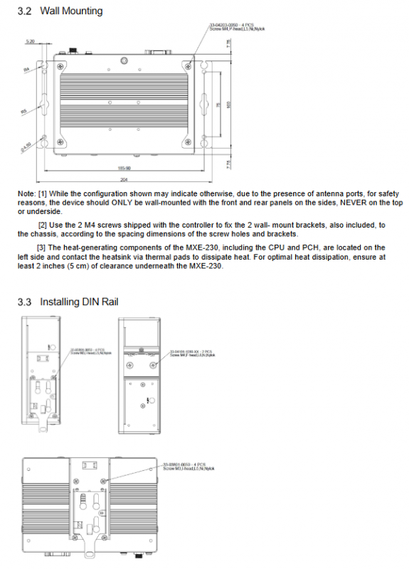
Wall mounted installation: Use matching M4 screws to fix the wall bracket; Important restriction: The antenna side can only be installed on the left and right sides of the device, and installation with the panel facing up or down is prohibited; On the left side of the CPU heating concentration device, a ventilation gap of ≥ 5cm is reserved at the bottom.
DIN rail installation: Use M3/M4 screws to secure the DIN bracket to the chassis and attach the standard DIN rail.
Mechanical Layout and Dimensions
Motherboard onboard connectors: DDR5 memory slot, M.2 M/E/B-Key, SATA signal+SATA power pin, AFM40pin expansion signal pin, RTC battery holder.
Complete engineering drawings: top view, front view, left and right side views, distinguishing differences in standard version/4COM/6COM/4LAN shell openings; The antenna bases ANT1 to ANT4 are distributed on both sides of the equipment.
Connectors and Jumpers
Front panel interface
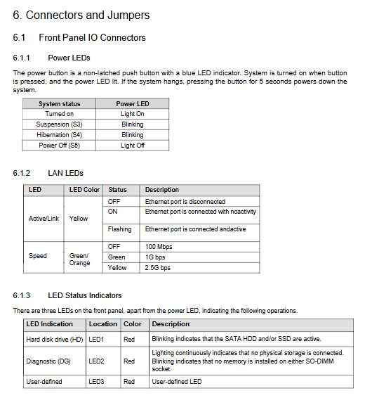
Power button: Non self-locking, press and hold for 5 seconds to force shutdown; LED status: Always on when turned on, S3/S4 sleep flashing, turned off when turned off.
Network port LED: yellow light Link Act; Speed indicator: Off=100M, Green=1G, Yellow=2.5G.
Status LED
HDD red: disk read/write flashing;
DG diagnostic red light: no storage, constantly on; No memory flicker;
User defined red LED.
The DP1.2 video port has a complete 20 pin pin definition and can be converted to HDMI/DVI/VGA.
DB9-COM serial port: Switching RS232/422/485 within BIOS, complete 9-pin signal definition.
DC power supply: circular DC jack, 12-24V input.
Internal onboard connector
SATA pin: SATA signal+3.3V/5V power supply, used for external 2.5 “SSD;
Three channel M.2 slot specifications (M-Key only PCIe; B-Key only USB; E‑Key PCIe+USB);
AFM 40pin expansion pin: PCIe, USB 2.0, SMBus, LPC can be connected to Linghua expansion board or customer customized ODM board;
RTC battery holder: BR2032 3V button battery.
AMI EFI BIOS Settings
Press Del to enter BIOS during startup; The menu is divided into Main/Advanced/Chipset/Security/Boot/Save&Exit.
Main page: BIOS version, CPU information, memory information, system date and time.
Advanced Menu
CPU configuration: E-core core number switch, SpeedStep, Turbo frequency, VT-X virtualization, VT-d, C-State sleep.
Power management: sleep S3/S4 switch; G3 power-off restoration power on option; RTC timed wake-up.
Hardware monitoring: board temperature, various voltage channels; Intelligent fan speed regulation (Auto/SMART FAN IV/Manual PWM).
BIOS watchdog WDT: Supports second mode, minute mode, and POST stage watchdog.
Onboard equipment: COM1-4 serial protocol (RS232/422/485), serial terminal resistor enable switch; Enable and disable internet access;
Serial console redirection Console redirection: baud rate, data bits, checksum, flow control, terminal type.
TPM2.0 configuration: Enable/clear TPM, PCR bank configuration, interface mode CRB/TIS.
Network stack: UEFI IPv4/IPv6 PXE, HTTP network boot.
Chipset chipset menu
Memory parameters, PCIe root port switch and speed; SATA controller; USB port separately enabled/disabled; BIOS lock.
Security menu: Administrator/user password, Secure Boot secure boot configuration.
Boot startup menu: NumLock, Quiet Boot, Fast Boot; Complete multi gear startup device priority setting.
Save&Exit: Save/discard modifications, restore factory default, EFI Shell startup.
Appendix A/B: Isolation DIO Digital IO (4COM/6COM/4LAN SKU specific)
The standard version MXE-231 does not have DIO hardware.
DIO Electrical Specifications (4/6 COM Version)
DI input: 2.5kV optocoupler isolation; Logic 0:0-1V; Logic 1:10-30V.
DO output: 2.5kV isolated MOSFET output; External power supply 5-30V; maximum single channel current of 500mA.
Complete pin definition for DB-26 DIO connector; Attached are internal circuit diagrams for input and output (optocouplers, freewheeling diodes).
Software usage steps for Windows
Download the DIO driver package from the official website and install MXE_SMBus_Sriver.exe;
Run StartDIO.exe with administrator privileges to initialize hardware;
DIO_CnsoleAPP.exe console tool for reading and writing DI/DO;
C++secondary development: header file matrix_dio. h, library file matrix_dio64. lib/dll.
4-LAN version DIO: DB60 large connector, 16DI+16DO isolated IO, complete pins, isolated circuit.
Safety instructions
Open maintenance requires cutting off the 12-24V DC power supply, restoring all chassis covers after repair, and then powering them back on.
The shell is running at high temperature, and it should be touched after cooling down to prevent burns.
RTC button lithium battery: There is a risk of explosion if the wrong model is replaced, and the waste battery is recycled in compliance.
Keep away from liquids and dust, and do not cover the heat dissipation fins; Only use UL/IEC certified 12-24V power supply.
Only for controlled industrial computer rooms, authorized technical personnel for maintenance; Water ingress, falling, and power damage must be returned to the factory.
Long term idle disconnection of power supply.