ADLINK MXE-210 series fanless X86 embedded industrial computer
Product Introduction
Product Positioning
The MXE-210 series compact all aluminum fanless industrial control computer is divided into MXE-211 (Intel Atom X7-E3950) and MXE-212 (Intel Atom X5-E3930). Targeting industrial automation, intelligent transportation, building management, and IoT scenarios; Support SEMA intelligent embedded management, equipped with watchdog, hardware monitoring, and remote management; Strong resistance to vibration and impact.
Core hardware features
CPU:MXE‑211:X7‑E3950; MXE‑212:X5‑E3930
Memory: Single DDR3L 1600 SO DIMM, maximum 8GB, standard 2GB
Display: DP1.2, maximum 4096 × 2160@60Hz , can be converted to HDMI/DVI/VGA
Network: 2 Intel I210IT Gigabit Ethernet ports; Supports IEEE1588, PCIe, WOL, and jumbo frames
Serial port: 2-channel DB-9 serial port, BIOS switchable RS232/RS422/RS485
USB:2×USB3.0 + 2×USB2.0 Type‑A
Storage: mSATA; Optional 2.5-inch SATA SSD; MicroSD card (up to 32GB)
Expansion: 2 full-size Mini PCIe slots, equipped with a USIM card slot along the way, supporting WiFi/Bluetooth/3G/4G LTE/LoRa modules
Internal expansion pin: 2-channel I2C, HSUART, internal USB2.0; Optional audio (MIC IN, Line Out, Speaker)
Power supply: 6-36V DC wide voltage DC input, 3P pluggable terminals; Recommended 40W power supply
Mechanical dimensions: 140 (W) × 110 (D) × 58 (H) mm; The total weight of the machine is 0.95kg; it supports DIN rail and wall mounted installation
Environmental indicators
Standard version: 0~+50 ℃; Wide temperature version -20~70 ℃; MXE-212 can be equipped with a heat dissipation kit to achieve -40~85 ℃ (requires industrial grade SSD)
Storage -40~85 ℃; 40 ℃, 95% non condensing humidity
Anti vibration 5Grms; 100G shock resistance; ESD contact ± 4KV, air ± 8KV
Certification CE, FCC Class-B, UL, CB
Power consumption reference: 3.6W when turned off; 11.2W when idle; 35.2W when CPU is fully loaded; 25W when the entire machine is fully loaded
Hardware Block Diagram of the Whole Machine
Showcasing Atom E3900 SoC and Memory DP、 Dual I210 Ethernet ports, USB, Realtek ALC269Q audio, dual Mini PCIe, mSATA, SATA, microSD, SEMA BMC, TPM2.0, multiple internal UART/I2C signal links.
Front panel I/O interface
Interface Description
The power button is not self-locking, long press for 5 seconds to force shutdown, with a blue power LED
Reset button hardware hard reset
Indicator light WDT watchdog yellow light (running flashing, timeout restart); HDD hard drive red light flashing for reading and writing; Standby blue light; 3-channel user-defined GPIO indicator lights
DP1.2 video output, complete DP pin definition
2 x Gigabit RJ45 yellow light Link Act; Green/yellow light indicates a speed of 10/100/1000Mbps
2 x DB9 COM COM1/COM2, BIOS switch RS232/422/485, complete DB9 pin definition
USB 3.0 × 2, USB 2.0 × 2 front A-port
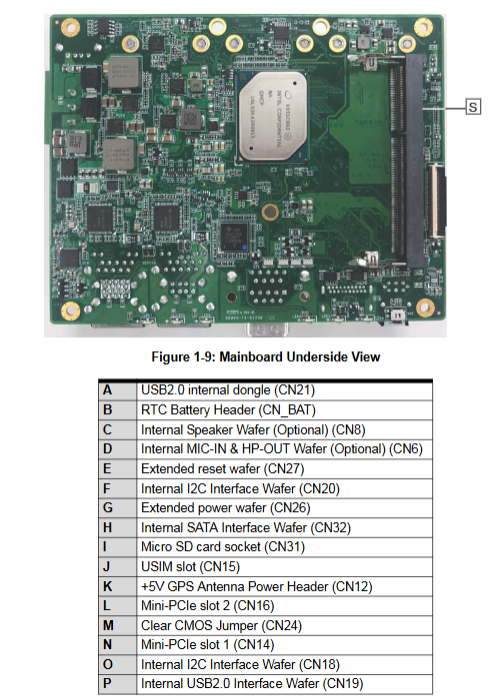
Internal onboard connector (motherboard pin header)
HSUART pin: with+3.3V, RX/TX/RTS/CTS/GND;
USIM card slot: used in conjunction with Mini PCIe 4G module;
Internal USB 2.0 pin arrangement;
Two sets of I2C pins with 3.3V/5V power supply;
Clear CMOS jumper: Short circuit pin clears BIOS and restores to factory default;
+5V GPS antenna power supply pin;
Internal SATA pin: used for external 2.5-inch SSD connection;
Expand power supply and reset pin bank;
RTC battery holder;
Optional speaker, MIC/headphone audio pin.
Quick Start Installation
All disassembly and assembly must be powered off; Disassembling the machine requires removing the bottom 9 screws.
Unboxing list: host, DIN rail bracket, screw kit, quick start guide; Power adapters and wall mounted kits are optional accessories.
Module installation steps
Mini PCIe mSATA: angled slot press down, secured with M2.5 screws;
Mini PCIe WiFi module: installation, antenna connection;
Mini PCIe 3G/4G LTE: First remove the side cover, insert the USIM SIM card, and then install the module;
DC power supply wiring: terminal V+/chassis GND/V —; LPS/SELV safety power supply must be used, and reverse polarity connection is strictly prohibited.
Installation method
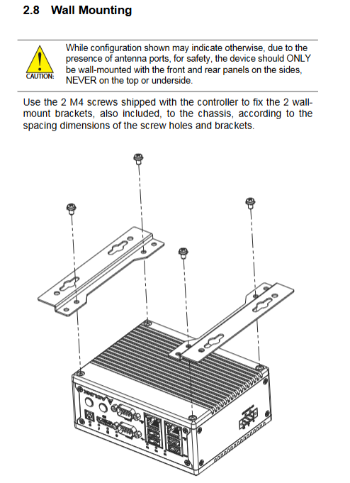
DIN rail: Use M4 screws to lock the bracket at the bottom of the chassis and attach the rail;
Wall mounted: Install wall mounted brackets; Important restriction: The device can only be mounted with the front and rear sides facing left and right, and the panel cannot be mounted with the wall facing up/down.
Heat dissipation reminder: The CPU heating components are concentrated on the left side of the chassis; Reserve a ventilation gap of ≥ 5cm above the equipment to ensure heat dissipation.
Driver and Application Software Installation (Windows IoT)
After installing the system, install the drivers in order and require administrator privileges:
Chipset driver
graphics card driver
Network card I210 driver
USB 3.0 driver
I/O peripheral driver
SEMA tool kit (watchdog WDT, DI/O driver)
SEMA Tool Core Capability
System health monitoring: CPU temperature, board temperature, runtime, input voltage, power consumption;
Hardware watchdog WDT: automatic hardware reset when software freezes and timeout occurs;
Users can use 1KB Flash storage;
Power on watchdog; Statistics of system power on and startup times.
Download the driver and SEMA installation package from the official website of Linghua.
Appendix A: AMI BIOS Complete Setup
Press DEL to enter BIOS during startup; Incorrect configuration of the Advanced menu can cause the device to fail to power on. You can use the motherboard Clear CMOS jumper to restore it to factory settings.
Menu grouping:
Main page: BIOS version, serial number, manufacturing date, MAC address; Total operating time of the system, number of power ups, and reason for startup; System date and time.
Advanced Menu
CPU configuration: number of cores enabled, virtualization VT-X, VT-d, Turbo turbo frequency, temperature protection threshold;
Graphics card configuration: GTT, Aperture, DVMT graphics memory allocation;
Onboard equipment: COM1/COM2 serial port mode (RS232/422/485) switch; Dual network port switch; Realtek audio switch; Serial console redirection Console redirection (COM1/COM2, baud rate, flow control, terminal type);
Power management: G3 power-off restoration and power on option; RTC timed wake-up; Network card WOL network wake-up;
USB configuration: XHCI Hand off, USB timeout parameter;
SATA configuration: mSATA, SATA port switch;
TPM2.0 safety chip switch;
Network Stack UEFI PXE;
System Management (SEMA BMC): View SEMA firmware version; Real time readings of hardware temperature, voltage, and power consumption; Watchdog indicator position, power on watchdog switch;
Misc: Operating system selection;
Network card parameters: Network port flicker positioning, Wake on LAN configuration.
Security menu: administrator password, user boot password, BIOS lock, Secure Boot secure boot switch.
Boot startup menu: NumLock, Quiet Boot, Fast Boot; Adjust the priority of the startup device.
Save&Exit: Save/Discard modifications; Load factory default settings; Supports EFI Shell startup.
Safety instructions
Open maintenance must completely disconnect the DC power supply, and after the repair is completed, it is necessary to restore all chassis covers before powering them on.
The casing of the equipment is running at high temperature. Stop the machine and wait for cooling before touching it to prevent burns.
Built in RTC lithium battery, replacing the wrong model will cause an explosion; Compliant recycling of waste batteries.
Stay away from liquids and moisture; Cannot cover the heat dissipation fins; Use certified 6-36V DC power supply.
Only for controlled industrial computer rooms, authorized technical personnel for maintenance; Water ingress, falling, and power damage must be returned to the factory for repair.
Long term disuse, disconnect power supply.