ADLINK NuDAM-6000 complete distributed RS-485 acquisition and control system
Basic Information
The overall system consists of four major categories of modules
Communication modules: ND-6510 (relay), ND-6520 (RS232 485), ND-6530 (USB-485), ND-6531 (addressable intelligent conversion)
Analog inputs AI: ND-6013 (RTD thermistor), ND-6017 (universal voltage and current 8-channel), ND-6018 (thermocouple 8-channel, built-in CJC cold end compensation)
Analog output AO: ND-6021 single channel AO, ND-6024 four channel AO (with 7 DI channels)
Digital IO/Counting: ND-6050/6052/6053/6054/6056/6058/6060 Relays/6063 Relays/6067 AC Relays, ND-6080 Counting Frequency Module
RS-485 bus hard engineering requirements
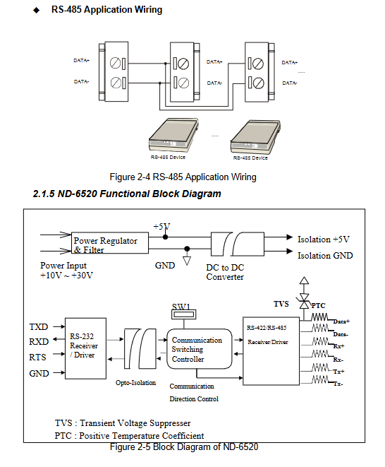
Both ends of the bus must be connected to a 120 Ω terminal matching resistor to suppress signal reflection;
Recommend shielded twisted pair cables, with multiple protective grounding points on the shielding layer;
Bus speed 1200~115.2Kbps; The maximum distance for a single segment is 1200m. If the distance exceeds 128 nodes, ND-6510 relay must be used;
The baud rate and checksum of all modules in the entire network must be completely consistent.
DEFILT * configuration pin
The vast majority of I/O modules and ND-6531 have a DEFILT pin: when powered on, this pin is short circuited to GND, and the module enters default mode: address 00, baud rate 9600, no checksum, used to modify address, baud rate, and checksum; It is strictly prohibited to connect to the power supply, and can only be suspended or connected to GND. The ND-6520/6510/6530 transparent conversion module does not have this pin.
Communication module
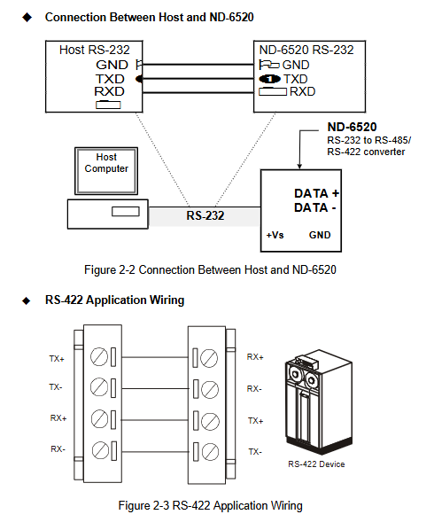
1. ND-6520: RS-232 to RS-422/485 converter
Isolation voltage 2500Vrms; DB9 connected to PC RS232, with two wire 485/four wire 422 output terminals;
Transparent hardware conversion, no module address, no programming required; Set the baud rate and data bit verification for dialing; Factory default 9600-8N1.
2. ND-6510: RS-485/422 signal repeater
Bidirectional regeneration signal, used to expand bus distance and node quantity; Fully independent RS-485 bus on both sides;
Transparent hardware relay, no address, no programming required; Up to 128 NuDAM modules can be mounted on each side of the bus.
3. ND-6530: USB to RS-232/422/485
USB 1.1 bus power supply, DIP switch selects interface mode; 2500V isolation; Install drivers to generate virtual COM ports; The upper level software is used as a regular serial port; Transparent conversion, no address.
4. ND-6531: Addressable RS-485 to RS-232 intelligent module (unique communication module with address)
Two modes: ① Addressable slave mode (participating in the NuDAM command system); ② Transparent direct mode (compatible with ND-6520);
The baud rates on the RS-485 and RS-232 sides can be independently set; Having the DEFAULT configuration pin requires initializing the allocation ID; supports RTS/CTS handshake, and supports host watchdog.
Distinguishing key points: 6520/6510/6530 are pure hardware transparent devices, without addresses, and do not respond to NuDAM commands; Only 6531 has an address and supports the full set of NuDAM instructions.
Analog input module AI
ND-6013: 3-channel RTD thermistor module
Support 2/3/4 wire Pt/Ni thermistor; 16 bit ADC; Sampling rate of 10SPS; Configurable temperature/ohm output; Supports multiple temperature ranges.
ND-6017:8 channel analog input
6 differential+2 single ended; 16 digits; Programmable range ± 10V~± 150mV, supporting 0-20mA (with an external 125 Ω sampling resistor); 5000Vrms isolation.
ND-6018: 8-channel thermocouple input
6 differential+2 single ended; Built in CJC cold end compensation, supporting J/K/T/E/R/S/B/N/C multiple thermocouples; Equipped with wire breakage detection function; Sampling rate of 3SPS.
The AI module supports offset calibration and full-scale span calibration; Multiple data formats can be selected, including engineering units, full-scale percentages, and hexadecimal complement.
Analog output module AO
ND-6021: Single channel analog output
12bit; Voltage output 0-10V; current output 0-20mA/4-20mA; 5000V isolation;
Support software adjustable output slope (slew rate); Support reading back actual output values; Support power on safety output value and watchdog safety value.
ND-6024: 4-channel bipolar ± 10V analog output, with 7 DI channels included
12bit, 4-channel differential voltage output; Simultaneously comes with 7 digital inputs; 5000V isolation, supporting watchdog safety output.
Digital I/O&Counting Module
ND-6050:7DI+8 open collection DO, no isolation, maximum DO current of 50mA
ND-6052: 8-way isolated DI (6 differential+2 single ended), 5000Vrms optoelectronic isolation
ND-6053:16 non isolated DI, supports dry contact and wet contact input
ND-6054:15 common power isolation DI, external 24V common power input
ND-6056:15 road common ground isolation open collection DO
ND-6058:28 channel programmable DIO; Simulate 8255 PPI mode 0; 24 programmable directions+4 fixed DI; 50 pin SCSI interface.
ND-6060: 4-channel relay output+4-channel isolated DI; 2-channel Form-A normally open, 2-channel Form-C conversion contacts; Contact DC 1A@30V .
ND-6063: 8-way Form A normally open relay output
ND-6067: 8-way AC high-power Form-A relay, contacts 3A@AC250V Used for exchanging loads.
ND-6080: Dual 32-bit Counter/Frequency Module
Maximum 20kHz; Support isolated/non isolated inputs; Programmable digital filtering suppresses noise; Support external door control; The counting alarm threshold can be set, and the alarm triggers DO output.
All DIO modules support: synchronous sampling broadcast command # * *; Programmable IO polarity reversal; The host watchdog timeout outputs a preset safe state.
Command Protocol Set
1. General format of commands
Guide code address (00-FF) Command code [Data] [Optional checksum]<CR (0x0D)>
Address: Two digit hexadecimal, broadcast address * *;
Checksum: Sum up all ASCII bytes of characters, modulo 0x100, high interference industrial field enabled;
Response:! Represents successful execution of the command;? Represents an error; Some broadcast commands (# * * synchronous sampling,~* * Host is OK feeding the dog) did not return a response.
Command categories
Universal commands (supported by all modules)
Set configuration%; Read configuration $Addr2; Read model $AddrM; Read firmware version $AddrF; Read the reset status; Soft reset.
To modify the baud rate/checksum, the DEFAULT pin must be grounded and powered on.
Simulate input AI commands
Read single channel/all channel AI; channel switch; CJC cold end control; Offset/full-scale calibration; Synchronous sampling.
Simulate output of AO command
Set output; 4mA/20mA calibration; Read the actual read back output; Save the power on safety output value.
Digital IO command
Synchronous latch sampling; Read DI; set DO output; 6058 Set IO direction; IO polarity reversal.
ND-6080 Counting Special Command
Set input mode, gate control, count value, digital filtering, alarm threshold, and clear overflow flag.
Watch Dog Special Instructions (Industrial Safety Core)
~Addr2: Set host watchdog: timeout period (100ms-25.5s)+fail safe output value;
~Addr3: Read watchdog parameters;
~**Feeding Dog Broadcast: The upper computer periodically sends this command, and the module receives it to determine that the host is alive; Unable to receive after timeout, DO/AO automatically switches to pre-set safety outputs to ensure the safety of on-site equipment.
Installation, initialization, and wiring
New module initialization process
① Short circuit the DEFAULT pin to GND and power on, the module enters the default state at addresses 00 and 9600;
② The upper computer uses ND-6520/65309600 baud;
③ Use NuDAM Administration tool to assign unique IDs, baud rates, and verifications;
④ Disconnect DEFAULT-GND;
⑤ Power off and connect to the existing RS-485 bus to confirm consistent baud rate verification across the entire network.
The steps for connecting to an existing network are: the standalone initialization must be completed first, and then the power must be turned off to connect to the bus to avoid address conflicts.
A large number of wiring example drawings: differential voltage, single ended voltage, current acquisition RTD、 Thermocouples, dry/wet contact DI, relay Form-A/Form-C wiring, isolated input-output wiring.
Data format and calibration
AI data output format options: engineering units, full-scale percentage, hexadecimal complement, ohms (RTD module).
Calibration process: Different firmware versions have different calibration commands for the ND-6013/6017/6018 AI module and the ND-6021/6024 AO module; The thermocouple module includes CJC cold end offset calibration.
Supporting software NuDAM Administration tool
Windows platform configuration and debugging tool;
Function: Scan all modules on the bus; Serial port parameter settings; Terminal manually sends ASCII commands; Graphically modify module parameters; Monitor IO status; Calibration simulation module; Save the configuration list of the printing module.
Key engineering precautions
RS-485: DATA+/DATA polarity cannot be reversed; Both ends of the bus must have a terminal resistance of 120 Ω; Try to minimize branch topology.
DEFAULT pin: only configured phase grounding, must be disconnected for normal operation; Do not connect to power supply.
Watchdog usage: Industrial safety projects must enable the host watchdog, and the upper computer will send~* * feeding dogs at regular intervals. Communication disconnection devices will automatically enter safety output to protect on-site processes.
The relay module strictly adheres to the rated parameters of the contacts and is strictly prohibited from overloading; Form-C is powered on by default with COM-NC connected.
Calibration of simulation modules requires a standard signal source, and commands may vary depending on the firmware version.
The module supports DIN rail installation; The power supply range is strictly+10~+30VDC, and reverse connection will damage the hardware.