ADLINK PCIe CPL64 PCIe x4 Interface Camera Link Image Capture Card
Product Overview and Core Specifications
Key Features
PCI Express x4 bus, compatible with x4/x8/x16 slots;
Choose one of the two working modes:
Dual Base: CN1 and CN2 are each connected to one Base specification Camera Link camera; The maximum bandwidth per channel is 255 MB/s
Single Medium: Only CN1+CN2 is used in conjunction to achieve a single Medium camera with a bandwidth of 320MB/s
Pixel clock up to 85 MHz;
PoCL (Power over Camera Link): Each channel outputs+12V, maximum 1A, with overcurrent protection, automatically recognizes ordinary cables/PoCL cameras;
Onboard 128 MB, 200 MHz DDR SDRAM image cache;
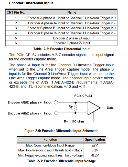
Encoder RS-422 differential input A/B/Z phase, up to 1 MHz;
Universal IO: 4-channel TTL DI, 4-channel open collector DO; 2-channel Line/Area trigger input; Exposure output;
Operating system: Windows XP/Vista, supports 64 bit memory addressing;
Development environment: VC++6.0, BCB6.0, VC++. NET, C #, VB.net;
Two Camera Link serial communication ports are used to interact with the camera serial port.
Electrical, mechanical, environmental
Board size: 167.65mm × 111.15 mm;
Power consumption:+12V maximum 0.5A;+3.3V maximum 1.6A;
Working temperature: 0-50 ℃; Storage -20~70 ℃; Humidity 5-90% RH without condensation.
Typical Applications
Line scan detection, 3D vision detection, industrial machine vision, supporting AreaScan and LineScan cameras.
Hardware interfaces, jumpers, and dialing codes
2.1 Interface
CN1, CN2 (MDR26, Camera Link video input)
Dual Base mode: CN1=Channel 0, CN2=Channel 1;
Medium mode: CN1 is responsible for controlling data, and CN2 is responsible for the second set of image data.
CN3 (D-SUB25) encoder+universal IO composite interface
RS-422 encoder: A+, A -, B+, B -, Z+, Z -; Z-phase level can be jumper selected RS422/TTL;
Two TTL Line/Area trigger inputs; Two Line Trigger Start inputs;
Line trigger bypass output, two-way exposure output;
4 DI inputs, 4 DO outputs; Board+5V output.
2.2 Jumper and DIP
JP1: Z-Phase Level Selection
Default: 1-2 short circuit → RS-422; 2-3 short circuit → TTL level.
SW1 Card ID (4-digit DIP dip code)
Use multiple cards simultaneously, set the card number to 0-15, and the software distinguishes different collection cards based on their CardIDs.
SW2 DO pull-up selection
DO is an open collector output; Each channel can independently choose whether to connect 10k Ω pull-up to+5V; enable pull-up when ON, disable when OFF.
Status LED (LED3-LED6)
LED3/LED5: Channel A/B PoCL+12V power indicator light;
LED4/LED6: Channel A/B acquisition status, flashing during acquisition.
2.3 Support trigger mode
FreeRun runs freely;
Line/Area Trigger (TTL/RS422 external trigger);
Encoder Input encoder trigger (line scan camera specific):
A-phase mode: A-edge counting;
AB phase mode: supports direction judgment, CW/CCW;
ABZ phase mode: Z phase serves as the zeroing starting signal;
Support delay counting and comparison counting, enabling the acquisition of one line of image for every N encoder pulses.
Hardware and driver installation
Hardware Installation
Anti static operation, the board can be inserted into PCIe x4/x8/x16 slots; Note that some motherboard x16 slots are only for graphics cards and may slow down to x1, so it is necessary to avoid them;
Power off the chassis, insert the board into the PCIe slot and tighten the screws.
WDM driver installation
Run the Setup installation package; lack. Net2.0 will prompt for installation NET Framework2.0;
Encountered a pop-up window without Windows logo testing under Windows XP, select ‘Continue Anyway’ to continue;
After installation, the computer must be restarted;
The device manager needs to recognize 4 devices:
ADLINK CPL64 Device
ADLINK CPL64 Frame Grabber
ADLINK CPL64 Port0/Port1 (virtual serial port, corresponding to Camera Link serial port)
Windows Vista system must disable UAC user account control, otherwise the card cannot function properly.
CamCreator tool software
CamCreator is a graphical debugging tool that does not require coding and is used for board detection, camera configuration, debugging, and image preview.
Main panel functions:
Devices panel: Identify the local PCIe CPL64 card and select channel CHO/CH1;
Cameras panel: Load/manage camera configuration files (cam files), built-in with multiple camera presets;
Parameters panel: Set image size, offset, Tap mode, trigger, encoder parameters; Parameter modifications take effect in real-time;
Counter panel: reads encoder count value, line counter, frame loss counter, supports reset;
I/Os&Software Trigger Panel: Read/Write DI/DO, Software Trigger Output;
Toolbar: Continuous acquisition, single frame snapshot, dual channel display, scaling, pixel value curve (Focus Value);
Console: Camera Link serial port terminal, capable of sending and receiving camera serial port commands, supporting ASCII/HEX mode;
Display window: displays the collected image, supports drag and drop, and box selection to enlarge.
The camera configuration file (cam file) is a text configuration file that saves all camera parameters, can be edited and modified, and is divided into multiple sections Section:CameraInfo、CaptureMode、ImageFormat、CameraControl、EncoderInput、LineAreaTrigger。
API Function Library (Secondary Development)
Provides C/C++, C #, VB.net interfaces, divided into two sets of DLLs: CPL64 image acquisition library and Camera Link standard serial port library.
Head Files&Library Files
C/C++:Cpl64.h + Cpl64.lib; Serial port: clallserial. h;
. NET:. cs/. Vb interface definition files;
Run dependencies Cpl64.dll and clallserial. dll.
API Function Categories
Board information function: obtain the number, model, hardware version, firmware version, and library version of devices;
Board control: OpenDevice opens channel, CloseDevice closes channel; LoadCamFile loads the camera configuration file; Save CamFile to save configuration;
Image acquisition
StartCapture starts collecting data; StopCapture stops;
SnapShot single frame snapshot; GetFrameRate to obtain frame rate;
DDroppedFrames reads the lost frame count;
Save Image to save BMP/JPG/TIF/PNG/Raw images;
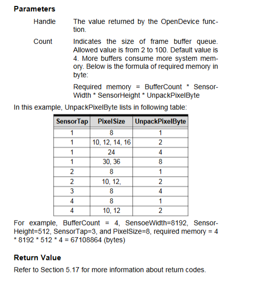
Reason for frame loss: The callback processing takes too long, the buffer is filled, and new frames are discarded; Countermeasure: Shorten callback processing time and increase the number of system buffers.
Capture Mode: Set line scan/surface scan; FreeRun / LineAreaTrigger / EncoderInput;
Image Format: Sensor Width and Height, X/Y Offset, Tap Count, Tap Layout Pattern, Pixel Depth, LVAL/DVAL Signal Enable, Data Packaging/Unpacking; Supports multiple pixel output layouts including single tap, dual tap, and quad tap.
Camera control CC1-CC4: CC1/CC2 can be configured as pulse output or regular DO output; Set pulse width and polarity; CC3/CC4 sets the output level.
Encoder input function: Set A/AB/ABZ mode; Direction CW/CCW; Delay counting and comparison counting; Read and reset the encoder count value.
Line Area trigger function: Trigger source TTL/RS422, polarity (rising/falling edge), reset row counter read/write.
TriggerOut output function: software triggers output, sets output polarity and pulse width.
GPIO functions: read DI, set DO, DI event callback.
PoCL power control: turn on/off Camera Link cable+12V power supply, read power status.
Buffer, callback, error code handling.
Standard Camera Link Serial API: Turn on/off serial port, set baud rate, read/write flush、 Obtain the number of available bytes, etc.
Important precautions
Medium mode can only be used in Channel0, and Channel 1 cannot be configured with Medium;
Encoder Input: The encoder trigger is only valid for Line Scan cameras;
The DO output has an open collector, and the SW2 dip controls whether to pull up+5V;
UAC on Vista system must be turned off, XP driver signature warning, choose to continue installation;
Duoka relies on SW1 to set CardID differentiation;
Some motherboard PCIe x16 slots only support graphics cards, which can slow down PCIe x4 devices and cause insufficient bandwidth and frame loss;
PoCL has overcurrent protection and automatically cuts off output in case of short circuit.