ADLINK PXES-2596 Gen3 9-slot PXI Express chassis
Product Overview and Core Features
PXES-2596 follows the PXI-5 Rev1.0 hardware specification; 9-slot configuration: Slot1 system controller slot+8 fully hybrid peripheral slots; Derivative model PXES-2596E: 1 system slot+8 hybrid peripheral slots+3 pure PXIe peripheral slots, totaling 12 slots; Two types of chassis backboards can be sold separately, using ATX power architecture without independent power boards, making it convenient for customers to integrate and develop them again.
Main Features
PCIe Gen3 high-speed backplane: dual link switching architecture, overall system bandwidth of 16 GB/s; All peripheral slots are independent PCIe Gen3 x4, with a maximum single slot bandwidth of 4 GB/s, far higher than the 1 GB/s of the old PXES-2590; The system slot supports dual x8 Gen3 links.
Power supply: Industrial grade 500W ATX AC power supply; Wide communication input; The maximum power consumption of the entire machine is 500W (including the power consumption of the system controller).
Cooling system: Dual 210.38 CFM fans; Bottom air inlet and rear air outlet; Heat dissipation derating: Single slot 58 W in 40 ℃ environment; Single slot 38 W in 50 ℃ environment; Fan supports AUTO intelligent graded speed regulation/HIGH forced full speed.
Synchronize clock and trigger
PXI_CLK10 (10 MHz), PXIe_CLK100 (100 MHz) global reference clock;
The internal SMA connector supports 10 MHz clock input/output and can be connected to an external reference source for multi chassis synchronization; Backplane PLL supports locking external 10M clock synchronization to generate 100M;
8-wire PXI trigger bus and interconnect adjacent modules on a single Local Bus.
Intelligent chassis monitoring: Multi point temperature sensors on the backplane, monitoring the voltage of various power sources and the speed of dual fans; Monitor configuration through SMBus and ChassisWatch software; Three color status LED alarm on the front panel.
Structural form: Desktop chassis with carrying handles, supporting the purchase of rack installation kits; Net weight 11 kg; working temperature 0-50 ℃.
Hardware specification parameters
1. Power parameters
AC input: 115-240 VAC, 47-63 Hz; 115V@8A , 230V@4A ; Total output power 500 W
DC output:
Output rail maximum current load regulation ripple noise
+5V 40 A ±5% 60 mV
+12V 32 A ±5% 120 mV
+3.3V 30 A ±5% 60 mV
-12V 1A ±5% 120 mV
5VSb standby 2 A ± 5% 60 mV
2. Clock specifications
PXI_CLK10: Maximum clock offset between slots of 300 ps; onboard clock accuracy of ± 25 ppm; Support external 10MHz input to cover local clock;
PXIe_CLK100: maximum inter slot offset of 100 ps, accuracy ± 25 ppm;
Internal SMA interface: Input 100 mVpp~5 Vpp, input impedance 50 Ω.
3. Heat dissipation parameters
Fan: 2 × 210.38 CFM; Airflow path: Inlet air from the bottom of the chassis and exhaust air from the rear;
Single slot heat dissipation: 58 watts in 40 ℃ environment; 38 watts in 50 ℃ environment;
Ventilation requirements for rack installation: Bottom air inlet ≥ 44.5mm (1U); Rear air outlet ≥ 76.2mm; unused slots must be equipped with filling baffles to ensure air ducts.
4. Mechanical parameters
PXES-2596 dimensions: 302.16 mm (width) × 177.8 mm (height) × 457 mm (depth);
Net weight of the whole machine: 11 kg;
Backboard size: 287.88mm × 165.45mm.
5. Environment and Certification
Working temperature: 0~50 ℃; Storage -20~70 ℃; Humidity 10-90% RH without condensation;
Shock: 30G half sine wave 11ms; random vibration;
Safety certification: EN 61010-1, EN 61010-2-201; EMI Class A; CE。
6. Backplane PCIe topology
Slot1 system slot outputs two PCIe Gen3 x8 chips, connected to two switch chips SW1 and SW2;
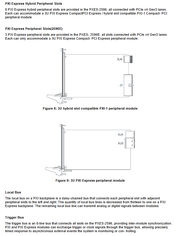
All Slot2-9 of PXES-2596 are independent PCIe Gen3 x4 hybrid slots;
PXES-2596E additional SW4 expansion, adding 3 Gen3 x4 peripheral slots (Slot10-12);
Compatible with traditional 32-bit 33MHz PCI modules, with built-in PCI bridging.
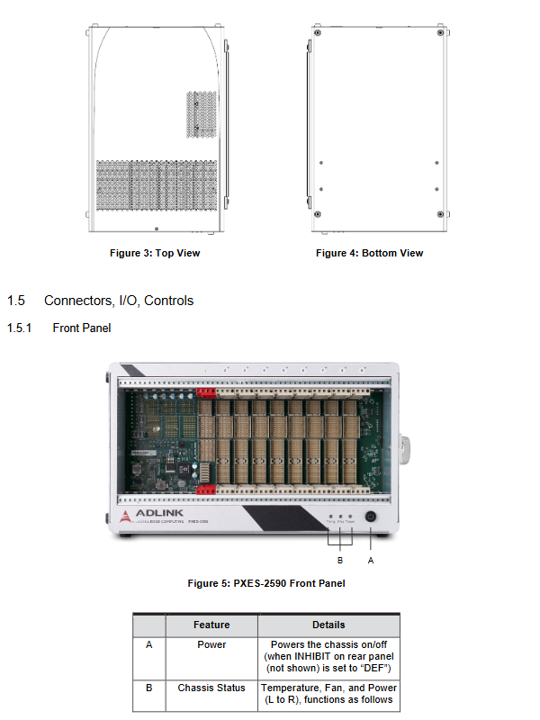
Panel interface, indicator lights
front panel
A: Power button; When the INHIBIT position on the rear panel is set to DEF, the front panel buttons are activated;
B: Chassis status tri color LED (from left to right)
Blue Power: Always on, power supply is normal; Flashing represents any power rail exceeding the ± 5% threshold;
Green Fan: The fan is always on and functioning normally; Flashing fan speed below threshold (default 800 RPM);
Amber Temperature: extinguished normally; The flashing temperature sensor reading exceeds the alarm threshold (default 70 ℃).
rear panel
INHIBIT switch: DEF=front panel button controls power supply; MAN=remote control of power on/off by DB9 Inhibit pin;
Fan mode switch: AUTO automatic graded speed regulation/HIGH forced full speed;
C13 AC power input port;
Chassis grounding pole, used for crimping safety grounding cables.
backplane
Backboard distributed multi-channel temperature sensors T1-T5; Internal SMA is used for 10 MHz clock I/O;
Bus resources: 8-wire PXI triggered bus; Local Bus; PXI_CLK10/PXIe_CLK100 reference clock.
Packing list and hardware installation
4.1 Packaging List
PXES-2596 chassis, AC power cord;
Fill baffle kit (1 3-channel baffle, 18 single slot baffles);
The rack installation kit is an optional item, part number 91-95115-0010, and is compatible with PXES-2590.
4.2 Hardware installation steps
System controller (Slot1): Recommended to be paired with Linghua PXIe-3987 embedded controller; Confirm that the CPU, memory, and storage of the controller are installed properly; Release the lock buckle, slide along the guide rail into Slot1, fasten the lock buckle, and tighten the panel fixing screw; The system slot supports a maximum of 4 slot width controllers.
Peripheral module installation (Slot2-9): Release the module lock, slide into the idle slot, fasten the lock, and tighten the screw; Idle slots must be equipped with filler plates.
It is strictly prohibited to hot plug PXI/PXIe modules. The entire machine must be powered off and plugged in, otherwise the hardware will be damaged.
4.3 Rack installation process
Remove the handle on the right side of the chassis and remove the rubber foot pad at the bottom of the left side;
Install optional rack brackets, with adjustable front and rear positions;
Fix the whole machine to the standard cabinet; The installation of the rack must ensure a ventilation gap at the bottom air inlet.
4.4 Startup process
Connect the AC power cord properly;
Confirm that the INHIBIT switch on the rear panel is DEF;
Press the power button on the front panel, the blue Power light will turn on, and the chassis will start.
Software Resources
1. ADLINK PXI Platform Services(APPS)
ChassisWatch: GUI chassis monitoring configuration tool that reads chassis status through system slot SMBus;
The PXES-2596 fan logic adopts multi-stage graded PWM speed regulation, without the need to manually set the target temperature.
|Stage | Heating trigger point | Falling threshold | PWM duty cycle|
|1|55℃|‑|30%|
|2|65℃|51℃|40%|
|3|73℃|61℃|60%|
|4|79℃|69℃|80%|
|5 | | | 75 ℃ | 100% full speed|
PXI Resource Manager and PXI Trigger Management Services comply with PXI-6 and PXI-9 software specifications.
2. MAPS Core Suite
DAQ driver, ACE device management tool, PXI configuration tool.
The monitoring function needs to be paired with a Linghua embedded controller; Third party controllers can develop their own monitoring programs using the SMBus protocol.
Troubleshooting and maintenance
Common Faults
The whole machine is not powered on: confirm the power cord and socket; Confirm that the INHIBIT switch on the rear panel is in DEF position;
Power blue LED flashing: One power supply voltage exceeds the limit; Dismantle all modules and retry; Continuously contact the manufacturer for the malfunction;
Fan green LED flashing: foreign objects blocking the fan or hardware failure of the fan;
Temperature amber LED flashing: Check the ventilation of the air inlet and outlet, and confirm that all empty slots are equipped with baffles; Contact the service provider if there is still an alarm despite normal ventilation;
System startup failure: All peripheral modules are unplugged and the fault locating modules are inserted one by one.
Maintenance points
The weight of the chassis is 11 kg. When handling, use the chassis handle and be careful not to injure it;
Before maintenance and cleaning, turn off the power and unplug the AC power cord; Wipe the shell and focus on cleaning the dust at the air inlet;
Internal maintenance of the chassis must be carried out by authorized technicians;
The device is only used indoors and has a maximum working altitude of 2000 meters.
Safety instructions
Before disassembling or plugging modules, the AC power supply must be completely disconnected;
Prohibit blocking ventilation holes; Stay away from liquid, high humidity and high temperature environments;
Built in backup lithium battery, there is a risk of explosion when replacing incorrect models;