ADLINK PXES-2780 18 Slot PXI Express Chassis
Product Overview and Core Features
PXES-2780 complies with the PXI-5 Rev1.0 hardware specification, with a total of 18 slots for the entire machine:
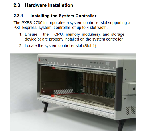
Slot1: System controller slot; Slot10: System timed ST slot; 10 hybrid peripheral slots; 6 pure PXIe peripheral slots.
The hybrid slot is compatible with CompactPCI, PXI-1, CompactPCIe, and PXIe 3U modules; Pure PXIe slots only support PXIe/CPCIe modules.
Core Features
Configurable PCIe Gen2 switch backplane
Two working modes: factory default 4-link x4 (bandwidth balanced allocation); Optional 2-link x8 (providing higher single channel bandwidth for some modules); The overall system bandwidth is 8 GB/s; Partial slots have a maximum bandwidth of 4 GB/s per slot; After modifying the mode, it is necessary to restart the chassis to take effect.
Power supply: Industrial grade 800W AC power supply; AC input 100-240V; suitable for high-density multi module configuration.
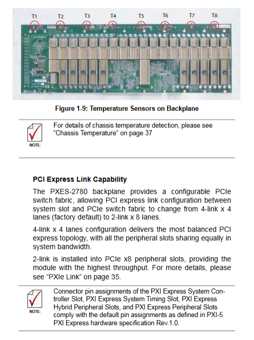
Cooling system: 3 sets of 185.9 CFM rear fans; Bottom intake and rear exhaust; Single slot heat dissipation capacity of 38.2W at 55 ℃ environment; supports AUTO intelligent speed regulation/HIGH forced full speed; The backboard is equipped with 8 temperature sensors T1-T8, and the fan speed is adjusted based on the highest temperature of all sensors.
Advanced Synchronous Signal System
Global clock: PXI_CLK10 (10 MHz), PXIe_CLK100 (100 MHz); The rear panel BNC supports 10MHz external clock input and output; Clock priority: System timing ST slot input>Rear panel BNC>Chassis built-in clock; The backplane PLL can lock external 10M to generate synchronized 100M clock.
Star trigger: The Slot10 system timing slot provides single ended PXI_STAR and differential PXIe-DSTAR star trigger signals.
Segmented programmable bridge contact transmission bus: The trigger bus is divided into three sections: A (1-6 slots), B (7-12 slots), and C (13-18 slots); The software can independently configure the inter segment connectivity/isolation of each 8 trigger lines, supporting 8 topology combinations.
Local Bus: A single interconnected bus connecting adjacent slots.
Chassis intelligent monitoring (dual interface)
SMBus: Install Linghua embedded controller, which can fully read and write status, modify thresholds, configure PCIe links, and configure trigger bus bridging;
RS-232 DB9 serial port: External ordinary computers can only read status, set alarm thresholds, and cannot modify PCIe links or trigger bridge configurations;
Monitoring objects: various power supply voltages, 8-channel backplane temperatures, and 3-channel fan speeds; Three color LED alarm on the front panel; Support remote INHIBIT power on/off.
Form: desktop/rack dual-use; Net weight 11.9 kg; working temperature 0-55 ℃.
Hardware specification parameters
1. Power parameters
AC input: 100-240 VAC, 50-60 Hz, maximum input 1200W; DC total available power 800W
Table
Output rail maximum current load regulation ripple noise
+5V 29.0A ±5% 50 mV
+12V 45.0A ‑ 120 mV
+3.3V 60.0A ‑ 50 mV
-12V 2.5A ‑ 120 mV
2. Clock indicators
PXI_CLK10: maximum inter slot offset of 300 ps; onboard clock accuracy ± 25 ppm;
PXIe_CLK100: maximum inter slot offset of 100 ps, accuracy ± 25 ppm;
BNC external input: 100 mVpp~5 Vpp, 50 Ω input impedance.
3. Heat dissipation and noise
Fan: 3 × 185.9 CFM; Bottom intake, rear exhaust;
Single slot heat dissipation: 38.2 W (verified at 55 ℃);
Noise: AUTO mode ≤ 46.3 dBA; HIGH full speed 64.5 dBA;
Rack ventilation: Bottom air inlet ≥ 44.5mm (1U); The rear air outlet must be ≥ 76.2mm; the vacant slot must be equipped with a filling baffle.
4. Mechanical parameters
Dimensions: 464.3 mm (width) × 191.4 mm (height) × 465.3 mm (depth)
Net weight: 11.9 kg
5. Environment and Certification
Working temperature 0-55 ℃; Storage -20~70 ℃; Humidity 10-90% RH without condensation;
Impact 30G half sine wave; Random vibration;
Safety EN61010-1; EMC Class‑A; CE certification.
6. Explanation of Backboard Slot Position
Slot1 system slot: supports embedded controllers with a maximum slot width of 4 slots;
Slot10 system timed ST slot: output star trigger; Can be used as a regular PXIe peripheral slot without star triggering;
Slot2‑9、 11-18: 10 mixing tanks+6 pure PXIe tanks; Some of the slots support PCIe x8 links.
Panel interface, indicator lights
front panel
Power button A; only valid when the back panel INHIBIT switch is in the DEF position;
Tri color status LED B (from left to right)
Amber Temperature: extinguished normally; Flashing any temperature sensor exceeding the default threshold of 70 ℃;
Green Fan: The fan is always on and functioning normally; Flashing fan speed below 800 RPM;
Blue Power: Always on, power supply is normal; Flashing any power rail voltage exceeding the ± 5% threshold.
Rear panel interface (emphasis)
BNC: 10MHz REF IN external clock input; 10MHz REF OUT clock output;
DB9-1 (Remote Monitoring) RS-232 serial port: external computer serial port monitoring (only reads status, sets threshold, cannot configure trigger bridge/PCIe link);
DB9-2 (Inhibit/Voltage Mon): Remote INHIBIT power on/off pin, which can directly lead out multiple DC voltages for multimeter measurement;
INHIBIT switch: DEF=front panel button control; MAN=remote control of power on/off by the INHIBIT pin of DB9;
Fan mode switch: AUTO automatic speed regulation/HIGH forced full speed;
C19 high-power AC power input port; Chassis grounding pole.
Note that RS-232 is for cross transmission and reception, and the cable needs to be Rx Tx crossed.
Packing list, hardware and rack installation
4.1 Packaging List
PXES-2780 chassis, power cord;
Fill baffle kit (1 3-channel baffle, 18 single slot baffles);
ADLINK All in One CD (monitoring software, drivers, manuals);
The rack installation kit is an optional item.
4.2 Hardware module installation
System Controller Slot1: Confirm that the CPU, memory, and storage of the controller have been assembled; Release the lock buckle, slide along the guide rail into the slot, fasten the lock buckle, and tighten the panel screws; Recommend pairing with Linghua PXIe-3975 controller;
Peripheral module Slot2-18: Release the module latch, slide into the idle slot, fasten the latch, and tighten the screw; Idle slots must be equipped with filling baffles; It is strictly prohibited to hot plug modules, and the entire machine must be powered off for plugging and unplugging.
4.3 Rack Installation
Remove the handle on the right side of the chassis and remove the bottom rubber foot pad;
Install and select rack brackets; The bracket hole supports front and rear depth adjustment, allowing the chassis to be retracted towards the interior of the cabinet, leaving space for front cables and Mass Interconnect components;
Secure the bracket to the standard cabinet using screws; The installation of the rack must ensure a ventilation gap at the bottom air inlet.
4.4 Startup
Connect the C19 AC power cord properly; Confirm that the INHIBIT switch is set to DEF;
Press the power button on the front panel, and the blue Power LED will light up.
System monitoring software PXES-2780 Chassis Remote Mon. Utility
The software runs on the Windows system; Comparison of two sets of communication interface capabilities
Table
Function SMBus (controller internal bus) RS-232 serial port (external PC)
Read the status of the chassis (voltage, temperature, fan speed) ✅ Support ✅ Support
Modify alarm threshold ✅ Support ✅ Support
Configure segmented trigger bus bridge routing ✅ Support ❌ not supported
Switch PCIe link mode (4-link x4/2-link x8) ✅ Support ❌ not supported
The software interface is divided into three modules: Connect Control, Remote Status&Control, and Chassis Status.
Connect Control
Choose SMBus or RS232 serial port; The serial port baud rate is fixed at 9600;
Chassis status log: Custom sampling period, log supports overwrite/append saving;
Threshold configuration: Save, load, and restore factory alarm configuration; Read MCU, FPGA, and backplane firmware versions.
Remote Status&Control (Chassis Control and Threshold Setting)
Trigger Bus configuration: software graphical interface, with 8 trigger lines independently configured to connect/isolate three sections A/B/C, and the configuration can save templates;
PXIe Link: Switch between 4-link x4/2-link x8 mode, and the modification will take effect after restarting the chassis;
Target Temperature: AUTO mode fan speed control logic: all sensors<25 ℃, fan duty cycle 40%; Linear acceleration starts when the temperature exceeds 25 ℃; The fan reaches the set target temperature at 100% full speed; The target temperature can be adjusted within the range of 25-70 ℃;
Fan Speed: The software can also switch between AUTO/Full full speed;
Alarm Threshold: Set the alarm thresholds for each DC voltage, temperature, and fan speed.
Chassis Status
Real time reading of all power rail voltages;
T1-T8, a total of 8 backplane temperatures;
3 fan speeds; Each parameter displays normal/abnormal status.
Troubleshooting and basic maintenance
Common fault phenomena
The whole machine is not powered on: confirm the C19 power cord and socket; Confirm that the INHIBIT switch on the rear panel is in DEF;
Power blue LED flashing: One power rail voltage exceeds the limit; Unplug all modules and retry; Continuously contact the manufacturer for the malfunction;
Fan green LED flashing: The fan is obstructed by foreign objects or the fan hardware is faulty;
Temperature amber LED flashing: Check the ventilation of the bottom air inlet and rear air outlet; Confirm that all empty slots are filled with baffles; If the ventilation conditions are intact and still alarm, contact the service provider;
System startup failure: Remove all peripheral modules, insert them one by one, and locate the faulty module.
Maintenance points
Net weight of the chassis is 11.9 kg; use chassis handles for handling to prevent injury;
Before maintenance and cleaning, be sure to turn off the power and unplug the AC power cord; Focus on cleaning the dust at the air inlet;
Internal maintenance must be operated by authorized technicians;
Built in backup lithium battery, there is a risk of explosion if the wrong model is replaced.
Safety instructions and technical support
Indoor use only; Maximum working altitude of 2000 meters; Pollution level PD2;
Before disassembling or plugging modules, the AC power supply must be completely disconnected; Prohibit blocking ventilation holes; Stay away from liquids, high temperature and humidity;
After the equipment is working, the temperature of the casing is high, which poses a risk of burns. It should be touched after cooling down.