ADLINK PXES-2788 series high-performance and high-power PXIe chassis
Product Overview and Core Features
Slot configuration
PXES-2788:18 slot: Slot1 system slot; Slot10 system timed ST slot; 8 hybrid peripheral slots; 8 pure PXIe peripheral slots.
PXES-2788E: 21 slots: Slot1 system slot; Slot10 system timed ST slot; 8 hybrid peripheral slots; 11 pure PXIe peripheral slots (19-21 slots are PCIe Gen3 x4, and the remaining peripheral slots are x8).
The hybrid slot is compatible with PXI-1, CompactPCI, and PXI-3U modules; Pure PXIe slots only support PXIe/CPCIe modules.
Core Features
PCIe Gen3 high-speed backplane
The system slot adopts dual link x8+x16 Gen3, and the overall system bandwidth is 24 GB/s; The vast majority of peripheral slots are independent Gen3 x8, with a maximum single slot bandwidth of 8 GB/s; The 19-21 slots of PXES-2788E are Gen3 x4 with a bandwidth of 4GB/s.
High power modular replaceable power supply, supporting dual power current sharing
The standard version has a maximum overall DC output of 1000-800W; the HP high-power version has a maximum output of 1700W;
The chassis has dual power slots, supports parallel current sharing of the second power supply, and does not support hot plugging; The power module can be disassembled and replaced on site to reduce MTTR.
Super strong heat dissipation capability (key upgrade)
Standard version: 3 × 210CFM rear fan; The HP high-power version adds an additional top 4 × 128CFM fan;
Single slot maximum heat dissipation of 102W (HP version, 0-40 ℃ Boost mode); Normal version up to 85W; system slot up to 200W;
Airflow direction: rear inlet air, top outlet air (different from the bottom inlet air of the old model 2780/2785);
Dual speed fan mode: Normal (≤ 60W/slot), Boost (high-power module); Speed range Auto intelligent speed regulation/High forced full speed; Backplane multi-channel temperature sensor, speed control takes the highest temperature of all sensors.
Advanced synchronization and timing system
Clock: PXI_CLK10 (10 MHz), PXIe_CLK100 (100 MHz), accuracy ± 1 ppm, low phase jitter; The clock interface is migrated to the front panel SMA (2780/2785 in the rear panel BNC);
Clock priority: Slot10 timing slot input>front panel SMA external input>chassis onboard clock; Backplane PLL can lock external 10M to generate 100M synchronous clock;
Slot10 system timing slot provides single ended PXI-STAR+three sets of differential PXIe-DSTAR differential star triggers;
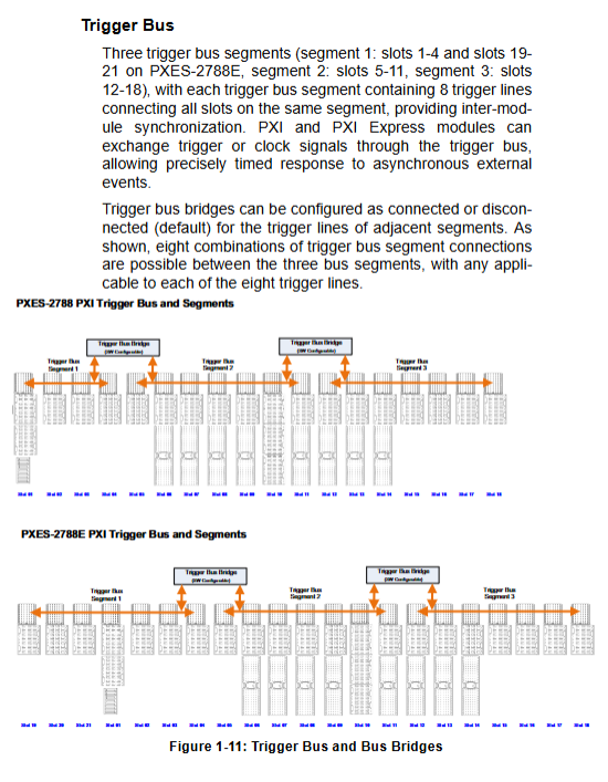
Three segment software can be configured to bridge the trigger bus, and 8 trigger lines can be independently configured for inter segment connectivity/isolation. The configuration supports saving templates;
Local Bus: Adjacent slots interconnect bus.
Chassis monitoring and hardware alarm
Complete all configurations using ChassisWatch software via the SMBus bus in the system slot;
Rear panel green terminal: Voltage Monitor/Remote Control, supports multiple power supply voltage sampling, FAULT fault output, INHIBIT # remote shutdown, PWRBTN # remote power button;
New security forced shutdown mechanism: If the voltage offset is greater than 8%, the fan continues to be below 600RPM for more than 60 seconds, and the temperature is greater than 100 ℃ for 3 seconds, the chassis will be directly forced to power off to protect the hardware;
Four color LED on the front panel: Power (blue), Fan (green), Temperature (amber), Fault comprehensive alarm; Normal alarm flashes at 1Hz; Emergency shutdown with a fast flashing frequency of 0.5Hz.
Attention: This model has cancelled the RJ45 network port web monitoring function of 2785 and can only access the chassis through SMBus (embedded controller).
Form: desktop/rack dual-use, net weight 11.9 kg; different versions have working temperatures of 0-45 ℃/0-50 ℃/0-55 ℃, depending on the power supply and fan configuration.
Hardware specification parameters
1. Power supply
AC input:
2400 PSU (HP version): 200-240VAC, dual channel x 13.3A;
1300 PSU (Standard Edition): 100-240VAC, dual 12-7A;
DC output capability (derating with temperature and AC input voltage)
Model Maximum DC Total Output
PXES‑2788‑HP / 2788E‑HP 1700W(0‑45℃@200‑240VAC) / 1000W(0‑50℃@200‑240VAC)
PXES‑2788 / 2788E 1000W(0‑55℃@200‑240VAC) / 800W(0‑55℃@100‑120VAC)
DC rail:+12V/+3.3V/+5V/-12V/+5Vsb, with specified load regulation and ripple noise indicators.
2. Key clock indicators
PXI_CLK10: maximum offset between slots 280ps; accuracy ± 1ppm; RMS phase jitter 0.44ps;
PXIe_CLK100: maximum inter slot offset of 100ps; accuracy ± 1ppm; RMS phase jitter of 2.41ps.
3. Heat dissipation and derating rules
Maximum heat dissipation condition for a single slot of the model
HP version 102W Boost mode, environment 0-40 ℃
HP version 85W Boost mode, environment 0-45 ℃
Standard version 85W Boost mode, 0-45 ℃
Standard version 60W Normal mode, 0-55 ℃
Constraint: When multiple slots are used simultaneously with high-power modules greater than 60W, the power consumption of some slot positions needs to be further limited to ≤ 72W.
Ventilation gap: HP version: rear ≥ 10.2cm, top ≥ 10.2cm; standard version: rear ≥ 10.2cm, top ≥ 4.45cm; empty slots must be equipped with filling/windproof baffles.
4. Mechanical parameters
Dimensions: Width 464.9mm (with handle)/444.4mm (without handle) x Height 194.8mm x Depth 482mm
Net weight: 11.9 kg; Packaging gross weight: 14.6 kg
5. Environment and EMC
Working temperature: 0-55 ℃ for regular version; HP-HP version 0-50 ℃;
Storage -40~71 ℃; Humidity 10-90% RH without condensation;
30G half sine 11ms impact; random vibration;
EMC Class-A, CE, FCC, ICES safety certification.
Panel interface and indicator lights
front panel
Power button; The button is only valid when the back panel INHIBIT switch is set to DEF;
Status LED (from left to right): Power blue, Fan green, Temperature amber;
SMA 10MHz REF IN (clock input), SMA 10MHz REF OUT (clock output).
Definition of LED Status
Phenomenon meaning
Corresponding light flashes at 1Hz, normal alarm: voltage exceeds limit/fan speed is low/temperature exceeds 70 ℃ threshold
All LED 0.5Hz fast synchronous flashing triggers safety forced shutdown protection (overvoltage, fan failure, over temperature of 100 ℃)
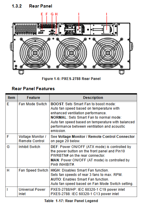
rear panel
Green terminal block Voltage Monitor/Remote Control: Multi channel voltage sampling, FAULT output, INHIBIT # remote shutdown, PWRBTN # remote power button;
INHIBIT switch: DEF front panel button control; MAN is remotely controlled by the INHIBIT # pin;
Fan Mode switch: Normal/Boost;
Fan Speed switch: Auto/High;
AC power input socket: C19 for HP version; Standard version C13; Dual power socket; Chassis grounding pole.
Packing list, hardware, rack installation, power replacement
4.1 Packaging List
PXES-2788 chassis body and power cord;
Fill baffle kit;
The rack installation kit is an optional item, and the part number is compatible with PXES-2780.
4.2 Module Installation
Slot1 system controller: Confirm that the CPU, memory, and storage are fully assembled; Release the lock buckle and slide it into the slot, fasten the lock buckle, and tighten the panel screws; Supports a maximum of 4 slot width controllers.
Peripheral module Slot2-21: Install in power-off state, tighten the locking buckle and tighten the screw; It is strictly prohibited to hot plug PXI/PXIe modules; Idle slots must be equipped with baffles.
4.3 Rack Installation
Remove the handles on both sides and the rubber foot pad at the bottom;
Install and purchase rack brackets, with adjustable bracket depth;
Fixed to the standard cabinet, with a focus on ensuring ventilation gaps at the back and top of the chassis (the air inlet of this machine is at the back and the air outlet is at the top, different from the old chassis).
4.4 Power module replacement
Completely shut down the entire machine and unplug all AC power cords;
Unlock the handle and directly extract the power module;
Align the new power supply with the guide rail and lock it in place; Restore the cable.
Dual power configuration only allows the same model of power supply; It does not support hot swapping and can only be replaced when the power is turned off.
4.5 Startup
Confirm that the INHIBIT switch is DEF, connect the AC power cord, and press the power button on the front panel.
Software resources and ChassisWatch functionality
Supporting software packages: ADLINK PXI Platform Services (APPS), MAPS Core;
Important: This series has removed the Ethernet web monitoring of 2785, and the monitoring configuration can only be run through the SMBus bus of the PXI embedded controller, running the ChassisWatch GUI.
ChassisWatch’s main functions
Chassis status monitoring: Read various DC power sources, multiple temperature sensors on the backplane, fan speed, firmware version, and log records;
Software configurable PXI trigger bus bridging: configure three-stage trigger bus routing on the graphical interface, and configure save/load templates;
Smart Fan control: can switch between Normal/Boost mode and Auto/High speed; AUTO mode speed regulation logic: temperature<25 ℃, fan duty cycle 40%; Linear acceleration above 25 ℃, with a maximum full speed of 70 ℃;
Alarm threshold configuration: voltage, fan, temperature alarm thresholds; View the security shutdown protection parameters;
Read the clock source status.
Troubleshooting and Maintenance
Common Faults
The whole machine is not powered on: check the AC power cord and socket; Confirm that the INHIBIT switch is in DEF; Check if the power module is securely plugged in; Confirm that both power supplies are functioning properly with dual power configuration.
LED 1Hz flashing: Normal alarm, run ChassisWatch to read specific fault items (voltage/fan/temperature); Check ventilation and baffle installation.
All LEDs flash rapidly at 0.5Hz, automatically power off: triggering hardware safety forced shutdown. Troubleshooting: Check if the fan is blocked or damaged; Whether the ventilation gap for heat dissipation meets the standard; Does the power consumption of the module exceed the rated power of a single slot; Whether the ambient temperature exceeds the limit. After troubleshooting, power off and restart to reset the protection latch.
System startup failure: All peripheral modules are unplugged and the fault locating modules are inserted one by one.
Maintenance points
The net weight of the chassis is 11.9 kg, and handles are used for transportation;
To maintain or replace the power module, the AC input power cord must be completely disconnected; Clean the dust from the rear air inlet and top air outlet with a focus on cleaning;
Built in backup lithium battery, there is a risk of explosion if the wrong model is replaced;
Internal maintenance is only authorized for technical personnel to operate.
Safety instructions
Indoor use only; Maximum working altitude of 2000 meters, pollution level PD2;
When disassembling or replacing modules, the AC power supply must be completely cut off; The air inlet of this chassis is located at the rear and the air outlet is located at the top. It is strictly prohibited to cover these two surfaces; Stay away from liquids, high temperature and humidity;
After the equipment is running, the outer shell should be kept at high temperature. Touch it after cooling to prevent burns