KUKA LBR iisy (MA_LBR_iisy V5) assembly manual
Product Hardware Description
Composition of Robot Body
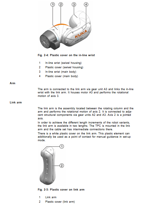
Base A1 rotating column, connecting rod arm A2-A3, forearm A4, inline wrist A5-A6, Commander wrist unit, and built-in cables for the entire machine. Each axis integrates triple monitoring of position sensors, torque sensors, and temperature sensors.
Commander wrist unit
LED status indicator light, enable switch, Back button, drag and drop handle, operation knob with OK confirmation;
A6 external interface, expandable gigabit network port and digital IO;
Output flange standard: ISO 9409-1-50-7-M6, with 7 M6 threads and a locating pin of diameter 6H7.
Permitted Use and Prohibited Misuse
Allow: moving tooling workpieces, processing, and workpiece transportation; Environmental conditions must be met and maintenance cycles must be followed. Prohibited: use as climbing tools, for carrying people and animals, outdoors in open spaces, in explosion-proof hazardous areas, in radioactive environments, or in underground mining; Unauthorized use results in loss of warranty.
Overview of Six Models
Model Rated load Maximum load Maximum arm span Body weight Repetitive positioning accuracy Protection level Remarks
LBR iisy 6 R1300 6 kg 6.9 kg 1300 mm 46.3 kg ± 0.05 mm IP54 standard model
LBR iisy 8 R930 8 kg 9.6 kg 930 mm 43.2 kg ± 0.05 mm IP54 standard model
LBR iisy 11 R1300 11 kg 11.72 kg 1300 mm 46.3 kg ± 0.05 mm IP54 standard model
LBR iisy 11 R1300 CR 11 kg 11.72 kg 1300 mm 46.3 kg ± 0.05 mm IP54 cleanroom ISO Class3 @ 40% magnification
LBR iisy 15 R930 15 kg 16.41 kg 930 mm 43.2 kg ± 0.05 mm IP54 standard model
LBR iisy 15 R930 CR 15 kg 16.41 kg 930 mm 43.2 kg ± 0.05 mm IP54 cleanroom ISO Class3 @ 40% magnification
Common parameters
Axis motion range: A1 ± 185 °; A2 -230°~+50°; A3 ±150°; A4 ±180°; A5 ±110°; A6 ± 220 °. Zero point positioning: A1=0 °, A2=-90 °, A3=90 °, A4=0 °, A5=0 °, A6=0 °.
Environmental conditions: Operating at 0~45 ℃; Storage -25~70 ℃; Operating humidity of 20-90% without condensation; Noise level is less than 67 dB (A).
Installation method: Ground, ceiling, wall, any inclination angle (± 180 °).
Cable: motor cable, data cable, equipotential protection ground wire; Optional A1/A6 extension interface package; The maximum length of the cable is 25 meters, and a maximum of one intermediate joint is allowed; The minimum bending radius is 5 times the outer diameter of the cable.
Load, flange load, base load
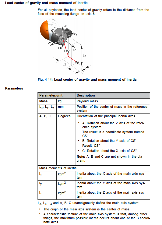
Load verification: The load mass, center of gravity coordinates Lx/Ly/Lz, and three-axis moment of inertia must be verified simultaneously; To use the KUKA Load tool for verification, it is necessary to input it into the controller. The maximum load is only allowed under the condition of the center of gravity origin. The mechanical arm body does not allow additional auxiliary loads. The document provides load curve diagrams for various models.
Wrist flange load: distinguish between normal operating conditions and emergency stop EMERGENCY-STOP conditions; This includes axial force Fa, radial force Fr, overturning moment Mk, and flange torque Mg. The emergency stop condition is an occasional condition and only static strength verification is performed.
Foundation load: Provide three installation conditions for the ground, ceiling, and wall, and provide vertical force Fv, horizontal force Fh, overturning moment Mk, and A1 axis torque Mr under normal/peak conditions. The base structure must be checked according to these parameters, and the failure of the foundation will result in a fatal risk of overturning and collapse.
Stopping distance and stopping time
Distinguish between Stop0 (cutting off the drive and directly closing the brake, causing significant damage to the brake and minimizing its use) and Stop1 controlled shutdown; Provide charts of stopping angles and stopping times for axes A1-A3 under different elongation rates and loads. It is recommended to conduct an annual brake function test.
Project Planning
Accelerating component wear conditions requires shortening maintenance cycles or consulting with KUKA technology: long-term extreme temperature operation, strong dust abrasion environment, continuous approaching performance limits, full power start of refrigeration unit, frequent single axis start stop, long-term vertical static posture, external continuous process forces. The robot is equipped with overheat protection, automatically shuts down when overheated, and can be restarted after cooling down.
There are two installation schemes: base substrate installation and rack frame installation; Fixed with positioning pins and bolts; It is necessary to ensure the flatness of the installation plane. Non ground installations must have the installation tilt angle recorded in the system software.
Cable laying: Separate the motor cable and data cable for routing; The cable does not bear tensile force; The cross-sectional area of the equipotential protection ground wire is ≥ 4mm ².
Interface: Base A1 interface (motor XD30, data XF31, protective grounding); A6 wrist optional expansion pack: Gigabit Ethernet, 24V IO interface.
4、 Transportation
Transportation must enter the official designated transportation posture;
Use qualified lifting equipment; Avoid impact and vibration; Dismantle the transportation protective parts upon arrival.
Start up and Resumption
5.1 Mechanical installation steps
Confirm that the robot is in a transport position; Verify the strength of the base;
Install positioning pins, position the robot, and tighten the fixing bolts diagonally and step by step;
Connect the equipotential protection ground wire;
Connect the motor and data cable, confirm that the connector is locked in place;
Power on, perform zero point calibration and input tool load parameters according to the controller manual.
5.2 Disabled manual mobile manipulator
Emergency power outage scenario mobile arm; Operators must undergo corresponding training.
Maintain Maintenance
6.1 Maintenance Overview
After 100 hours of operation, all fasteners undergo torque re inspection;
5000 operating hours or at the latest 1 year: replace A5 synchronous toothed belt (core maintenance item);
7-year comprehensive inspection of the entire machine, contact KUKA service.
6.2 A5 synchronous belt replacement process
Safety: The system is locked and tagged, and the A5 joint is fixed to prevent rotation;
Remove the wrist guard; Loosen the tensioning mechanism and remove the old toothed belt;
Assemble a new synchronous belt, use a frequency meter TSM alpha-2 to measure the vibration frequency, and complete the initial adjustment;
Release the fixed fixture, perform multiple motion cycles on the joints, retest tension, and make secondary adjustments;
Reinstall the protective cover; Complete A5/A6 zero calibration; T1 mode low-speed trial operation.
Distinguish between two different sets of gear belt parameters: 6R1300/11R1300 series are one set; The 8R930/15R930 series is another group.
6.3 Cleaning
Cleaning in power-off state; Do not use high-pressure water guns or compressed air to blow the sealed bearing parts; Use solvent-free water-soluble cleaning agents; Clean and perform anti-corrosion protection.
Repair Repair
ISO output flange can be replaced separately; The document provides disassembly and assembly steps.
Except for maintenance items explicitly stated in the manual, all other repairs must be authorized by KUKA for service; High strength bolts must be replaced with new parts after loosening and cannot be reused.
Decommissioning, storage, and disposal
Dismantling and retiring: moving robots to transport positions; Power off the entire machine and disconnect all cables; Remove the fixed bolts and lift off the base.
Storage: Clean the robot and provide sealing protection; Avoid condensation and direct sunlight, and comply with temperature and humidity indicators.
Scrap disposal: Classify and dispose of materials such as aluminum alloy, steel, copper, electronic components, lubricating grease, sealant, etc. according to local regulations.
Optional Accessories Options
A1 external interface extension package;
A6 wrist energy supply system connector package (Gigabit+IO), including installation and debugging steps;
Various alternative cables: data cables, grounding conductors.