



KUKA KR IONTEC HO Robot Assembly Manual
The assembly manual for KUKA KR IONTEC HO series sanitary oil lubricated six axis industrial robots covers three models: KR 50 R2100 HO, KR 50 R2500 HO, and KR 70 R2100 HO. It includes product instructions, safety specifications, technical parameters, planning and installation, transportation, commissioning and start-up, maintenance, repair, retirement storage and disposal, options, appendices, and all other contents. HO stands for Sanitary Oil, targeting the secondary food industry. The gearbox uses specialized Optileb GT 1800/460 lubricating oil.
Product Description
Composition of Robot System
Robot arm body, connecting cables, robot controllers (KR C4/KR C5), smartPAD teaching pendant, software, optional accessories. All three models are 6-axis serial joint robots, with main components including built-in wrist, linkage arm, rotating column, base frame, and electrical components. A1-A3 with mechanical end stop, only for equipment protection; Personnel safety relies on the Safe Robot function of the controller or optional mechanical axis limit.
Installation Form
Support ground, wall mounted, suspended ceiling, and installation at any tilt angle of 0-180 °; When not installed on the ground, the tilt angle must be configured in the WorkVisual software. Incorrect settings can cause overload and abnormal motion.
Prohibited misuse scenarios
Prohibit climbing and trampling, operating beyond parameters, direct contact with food, lack of safety equipment, carrying people and animals, outdoor use, explosion-proof areas, radioactive environments, and underground mining; Misuse will result in loss of warranty.
Wrist flange
Cast flange D=100, hole diameter 100 mm, 9 M8-10.9 threads, engagement depth 14-20 mm, locating pin Φ 8 H7, following ISO 9409-1.
Core Technical Data
KR 50 R2100 HO
Rated load of 50 kg, maximum load of 61 kg (requires KUKA verification of load conditions); The self weight is about 533 kg; the repeatability accuracy is ± 0.05 mm; the working envelope volume is 36 m ³.
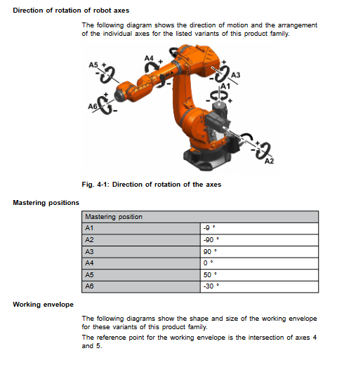
Range of motion for each axis: A1 ± 185 °; A2‑175°~+60°; A3‑120°~+165°; A4 ±180°; A5 ±125°; A6 ± 350 °.
Maximum speed of each axis under rated load: A1 180 °/s, A2 175 °/s, A3 175 °/s, A4 250 °/s, A5 250 °/s, A6 360 °/s.
KR 50 R2500 HO
Rated load of 50 kg, maximum load of 61 kg, extended working radius; The range of axial motion is the same as KR50 R2100 HO.
KR 70 R2100 HO
Rated load of 70 kg, maximum load of 85 kg; A1-A3 have the same stroke, but the maximum shaft speed decreases: A2 158 °/s, A3 160 °/s, A4/A5 230 °/s, A6 320 °/s.
Environmental conditions
Operating temperature: 0~55 ℃; Storage and transportation -40~60 ℃;
Cable: Supports KR C4 and KR C5 controllers; Motor cables, data cables, 16mm ² equipotential grounding conductors; The cable length can be selected from 7-50 meters, with a maximum length of 50 meters.
Stopping distance and stopping time
Following DIN EN ISO 10218-1, distinguish between STOP 0 (category 0, uncontrolled emergency stop) and STOP 1 (category 1 controlled stop); Composite axis motion will increase the stopping distance; The manual provides charts of stop angles and stop times for each axis under different extension lengths, loads, and program magnifications of POV; The STOP 0 value is a simulation+test reference value, and it is recommended to conduct actual testing under actual project conditions.
Basic Load
The robot outputs force and torque to the base during motion, and the manual provides the force parameters of the base; The additional load of A1 rotating column and A2 connecting rod arm is not included in the factory foundation load. When calculating the foundation, an additional vertical force Fv must be added. The minimum grade of foundation concrete is C20/25.
Planning
Two installation options:
R300 × 400 (part number 0000-309-857, approximately 26.7 kg) with centering base kit: used for concrete foundation, including base plate, locating pin, M20 bolt, chemical anchor bolt; Insufficient flatness of the foundation requires the use of leveling mortar, and attention should be paid to not filling the bolt holes with mortar.
Rack mounted installation (0000-331-410, approximately 2.3 kg): Install directly onto the customer’s steel structure and slide table adapter plate, relying on cylindrical and flat pins for positioning, and tighten 8 M20 bolts diagonally in multiple steps.
Warning: Installing the wrong robot may cause it to overturn. The integrator ensures the stability of the entire machine. Provide the base size diagram, concrete edge distance, and reinforcement requirements for reinforcing bars.
Transportation
Mode of transport
Forklift transportation: Use fork slots on both sides of the column, with a minimum load capacity of 2 tons for the forklift; Crane lifting: use approved M12 lifting points; The robot must first be moved to the designated transport posture, and the manual provides the center of gravity coordinates for each model; Prohibit the use of non certified lifting equipment.
Startup and Re Debugging
Startup process for two types of installations
1) Installation process of the base kit: Install the fork groove lifting device → Place the forklift in place → Install the positioning pin and bottom plate bolt → Adjust the level and perform leveling grouting if necessary → Fix the chemical anchor bolt → Remove the fork groove lifting device → Connect the cable → Finish the work. 2) Rack mounted installation process: Install fork groove lifting equipment → Clean the customer’s installation surface, install positioning pins → Lower the robot vertically, tighten M20 bolts diagonally in stages → Remove lifting equipment → Connect wires.
The lifting fork slot must be removed before starting, otherwise serious equipment damage may occur.
Cable Wiring
The tightening torque of the grounding conductor M8 nut is 15 Nm;
KR C4: Motor cable X20-X30, data cable X21-X31;
KR C5: motor cable XD30, data cable XF31; The tightening torque of the motor connector is 3 Nm; the data plug needs to be securely fastened with a snap lock;
After completing the wiring, it is necessary to verify the equipotential according to VDE0100 and EN60204-1; WorkVisual sets the actual installation posture (ground/wall mounted/ceiling).
Definition of Cable Pin
Provide complete pin allocation for KR C4 and KR C5 motor cables, data cables, and grounding cables;
A4 axis overtravel protection
A4 comes with an angle indicator and positioning pin. After losing the master point, it is necessary to determine the positive and negative directions based on which side of the angle mark the pin is on, and then perform a pre calibration notch operation.
Maintenance
The gearbox oil uniformly uses Optileb GT 1800/460 special oil, with filling capacities for each shaft: A1: 5.66 L; A2: 2.49 L; A3: 1.00 L; A4: 0.33 L; A5: 0.60 L; A6: 0.24 L.
Maintenance checklist
A1 cable kit inspection and lubrication: visually inspect the sheath, apply lubricating grease with a brush, and move A1 to evenly distribute the grease;
Oil change for each shaft gearbox: The gearbox should be at operating temperature to prevent burns; Ventilate and release pressure before draining oil; The tightening torque of M18/M10 magnetic plug is 20 Nm; the oil level is based on the lower edge of the inspection hole; Partial shaft oil change requires swinging to a specific posture (e.g. A4 requires A2+A3=-68 °); After changing the oil, conduct a T1 mode trial run to check for leaks.
Robot cleaning: Only solvent-free, water-soluble, chlorine free, non strong acid-base neutral cleaning agents are allowed, and steam spraying is prohibited.
Safety reminder: Once high-strength bolts (grade 10.9 or above) and stainless steel 70/80 bolts are loosened, they must be replaced with new parts and cannot be reused.
Maintenance (motor replacement, electrical system)
General steps for replacing A1/A2/A3 motors
A2 motor replacement must use a sling to fix the connecting rod arm; A3 motor replacement requires a sling to secure the built-in wrist and upper arm to prevent self weight from falling.
Unplug the motor and encoder right angle connectors; Remove the bolts; Remove the motor and protect the gear input shaft from dust.
New motor: Remove the rust proof protective layer; Apply Microlube GL261 lubricating grease thinly on the spline area; Check the O-ring; Install the motor without tilting it; Tighten the bolts diagonally multiple times; Insert the connector back to ensure that the anti rotation buckle is in place.
Restore the cover plate and remove the lifting device; The axis must be recalibrated for mastering; T1 mode test run.
Composition of Electrical System
A1-A3 cable assembly+micro RDC box; A4-A6 wrist cable; All motor power supply, brake, temperature, RDC encoder signal lines; X30/X31/PE external interface at the rear of the main body base. The document includes a complete set of wiring schematics: drawings for each axis motor, brake, temperature feedback, RDC encoder, and protective grounding circuit.
Retirement, storage, and disposal
Shutdown and disassembly process
The robot moves to the transport posture; Emergency stop and power outage; Remove the tool peripherals;
Disconnect the sealing gas (casting plate), cable, and grounding conductor; Loosen 8 M20 base bolts; Vertical lifting, pay attention to protecting the positioning pin to prevent the body from popping open and injuring people.
Storage Conditions
Store in a dry and dust-free place, reduce temperature fluctuations, avoid condensation, and direct sunlight; Storage temperature -40~60 ℃; After cleaning the robot, cover it properly and remove the tool attachments.
Scrap disposal
The disassembly of the body distinguishes between cast aluminum, copper, cast steel, steel, and electrical components, and is classified and recycled according to local regulations.
options: manual release device
Manually move the brake of each axis in power-off state: install and release tool kit; Remove the motor cover plate; Use the release tool to overcome the brake resistance and rotate the joint.
Important warning: After manually moving the shaft with power off, all shafts must be recalibrated to zero, otherwise it may cause collision and injury. Provide the installation steps for release tools, arrow label stickers, and torque parameters.


