KUKA KR 360 FORTEC Heavy duty Six Axis Industrial Robot
KUKA heavy-duty six axis industrial robot mechanical body assembly manual, aimed at system integration, debugging and maintenance personnel with advanced mechanical and electrical professional knowledge; Robots belong to semi-finished products, and integrators are responsible for CE compliance and risk assessment of the entire equipment. The product family includes multiple sub models, supporting ground installation (F), ceiling installation (C), casting reinforced F variant, and ceiling casting C-F variant. It covers three major series of heavy-duty models: KR360 R2830, KR280 R3080, and KR240 R3330, and is compatible with KR C4/KR C5 controllers.
Product Description
Composition of a complete robot system
Robot arm body, robot controller, smartPAD teaching pendant, connecting cables, system software, optional accessories.
Robot body structure
6-axis series articulated robotic arm, cast+lightweight alloy structure, driven by AC servo motor; A2 axis is equipped with a hydraulic pneumatic balance cylinder system to counteract the gravity load of the connecting rod; Main components: base frame, rotating column, connecting rod arm, forearm, Inline hollow wrist.
F variant: Strengthen the wrist, apply pressure inside the arm to prevent dust and moisture, and adapt to harsh working conditions such as high temperature and dust casting; Dry compressed air needs to be connected.
C variant: Inverted ceiling installation; The working mode of the balance cylinder is opposite to that of the ground version.
C-F: Ceiling+casting reinforcement, dual variant.
Electrical components: RDC box, multifunctional housing MFH, complete set of motor/signal cables; External connector at the rear of the base.
Optional accessories: mechanical hard limit, shaft angle limit module, no drive release device (manual release brake).
Designated Use and Misuse
Designated use: for transporting fixtures and jigs, workpiece processing, material transportation, using within specified environmental parameters, and fully following the assembly and maintenance manual.
Misuse (loss of warranty): carrying people/animals, outdoors, explosion-proof, radioactive, underground operations, climbing and stepping, operating beyond parameters, and operating without safety protection.
Robots are semi-finished products that must be integrated into a complete system to achieve CE compliance.
Technical Data
Contains KR360 R2830/KR280 R3080/KR240 R3330, each model is further divided into F, C, and C-F variants.
Basic Common Parameters
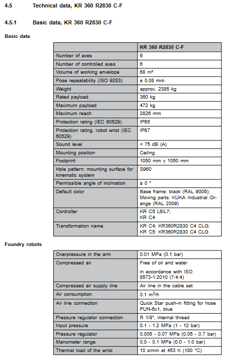
Repetitive positioning accuracy ISO9283: ± 0.08 mm; noise<75 dB (A); Protection level: IP65 for the main body; F-variant wrist IP67.
Environment: Operating temperature of 10~55 ℃; Storage -25~60 ℃; Environmental level 3K3.
The weight ranges from approximately 2385 to 2421 kg; Base installation hole position S960.
Flange standard ISO 9409-1-200-11-M12, with 12 M12 to 12.9 grade bolts.
Cable: Suitable for KR-C4/KR-C5 controllers, motor cable, data RDC cable, equipotential grounding wire; The maximum cable length is 50 meters.
Core specifications of each model
Model Rated Load Maximum Load Maximum Arrival Installation Method
KR360 R2830 360 kg 472 kg 2826 mm ground
KR360 R2830 F 360 kg 472 kg 2826 mm Ground casting reinforcement
KR360 R2830 C 360 kg 472 kg 2826 mm Ceiling
KR360 R2830 C-F 360 kg 472 kg 2826 mm Ceiling Casting Reinforcement
KR280 R3080 280 kg 356 kg 3076 mm ground/F casting plate
KR240 R3330 240 kg 297 kg 3326 mm Floor/C Ceiling/F Casting
The F casting machine needs to be connected to dry and clean compressed air, and the arm should maintain an overpressure of 0.1 bar to prevent dust and water vapor from entering.
Axis Parameters and Load Chart
Range of motion angles for each axis and rotational speed under rated load; The load mass and moment of inertia must be verified simultaneously, and the KUKA Load tool must be used to calculate the operating conditions. The load parameters must be entered into the controller, otherwise it will cause gear/motor overload and shorten the service life.
Include load Lxy Lz load curve chart; The axial force, radial force, and overturning moment borne by the flange (divided into normal operation and emergency stop conditions).
Additional loads: Auxiliary loads (pipeline packages, shields) can be installed on columns, connecting rods, and small arms, with allowable weights and installation hole drawings provided.
Base Load (Key to Civil Engineering)
Output robot motion transmitted to the base: vertical force, horizontal force, overturning moment, A1 rotation torque; Distinguish between normal values and peak values (excluding safety factors, additional safety factors are required for civil engineering design); The load direction of the suspended ceiling version is reversed.
Stopping distance and stopping time
According to DIN-EN-ISO 10218-1; Provide charts showing the stopping angles and times of axes A1/A2/A3 at different speed ratios (POV) and load ratios for STOP0 (cutting off power) and STOP1 (path keeping stop); The stopping distance of multi axis compound motion will increase.
Nameplate Labels and REACH Regulations
Multiple warning nameplates for the main body: high pressure, high temperature, danger zone, transportation posture, balance cylinder pressure warning. The nameplates must not be torn off and must be replaced if they are blurry.
REACH regulation SVHC high concern substance information can be accessed through the KUKA Xpert system.
Project Planning and Design
Warning for harsh working conditions: Long term close to temperature limits, abrasive environment, full power cold start, high-frequency short reciprocating motion, continuous static force, external process force will accelerate component wear and require shortened maintenance cycles. It is recommended to consult KUKA services.
Base selection
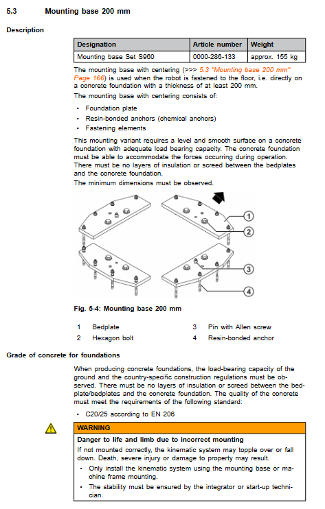
175mm base S960: concrete foundation with a thickness of ≥ 175mm, concrete grade C20/25, chemical anchor bolt installation; Insulation layer/leveling mortar interlayer is prohibited between the foundation and the bottom plate.
200mm base; Installation of the entire machine frame (machine rack installation).
Civil engineering safety: It is necessary to ensure anti overturning and prevent the risk of robot tipping and falling.
Cable selection, distinguishing motor and data cable specifications, grounding and equipotential requirements between KR-C4 and KR-C5.
Transportation
The robotic arm must be placed in the designated transport position and all external cables must be removed; Use body lifting points for transportation to avoid impact and vibration.
Startup and Restarting
Installation of ground robots; Installation of ceiling robots; Base installation process, bolt torque specifications.
Cable distinction between two sets of controllers KR C4 and KR C5: motor cable, data RDC cable, and interface and connector instructions for protective grounding/equipotential cable.
Preconditions for operation: qualified foundation, sufficient torque of fasteners, no transportation damage, adaptation to ambient temperature to eliminate condensation, and all cables are locked; Complete security function testing.
Maintenance
Power off, lock and tag before maintenance, ESD protection; Provide a complete maintenance cycle summary table. Main maintenance projects:
Lubricate O-ring (A4/A5 axis) with grease;
Regular inspection of the liquid pressure balance system;
A4-A6 drive shaft inspection;
Oil change for all 6 shaft gearboxes: steps for draining and injecting oil separately;
Cable package lubrication;
Replacement of balance cylinder components: divided into disassembly and assembly steps for ground models and disassembly and assembly steps for ceiling models (mechanical locking of the robotic arm before disassembly and assembly);
Robot body cleaning: power off, neutral cleaning agent on soft cloth, prohibit high-pressure water spraying; Complete maintenance and retest all security functions.
Maintenance
Motor replacement: A1/A2/A3 motor disassembly and installation process;
Disassembly and assembly of A4-A6 wrist motor and universal drive shaft assembly, distinguishing between two types of universal shaft structures: those with fastening screws and O-rings;
Electrical wiring instructions.
Discontinuation, Storage, and Scrap Disposal
Ground/ceiling robot shutdown and disassembly process;
Long term storage: take protective measures;
Scrap: Machinery, hydraulic oil, and pressure components should be classified and disposed of according to local waste regulations.
Options
Release device without driver: When the driver is powered off, manually release the brake to move the robotic arm. The operation steps and end reset.