SUMITOMO GND series slotting and cutting tools
Core product advantages
The high rigidity integrated blade body (made of mold steel material) adopts an integrated mono block structure, which reduces vibration by about 30% compared to traditional clamp type blade holders, suppresses chatter, allows for higher feed rates, reduces blade breakage and workpiece surface vibration patterns, and improves machining stability.
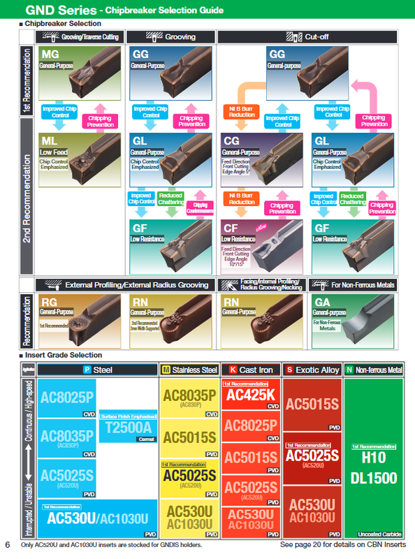
Rich chip breaker system: There are a total of 10 types of chip breakers, covering cutting, cutting, transverse tool turning, profiling, and non-ferrous metals.
Complete brand matrix: compatible with Sumitomo’s mainstream brands that have appeared in the previous manual: AC8025P/AC8035P (steel), AC425K (cast iron), AC5015S/AC5025S/AC520U/AC530U (high-temperature alloy), AC1030U (precision small parts); There are also metal ceramic T2500A, uncoated H10 (aluminum copper), and CBN blade support for quenched steel and powder metallurgy.
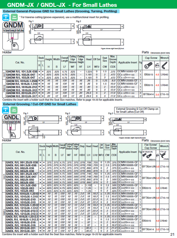
Internal cooling tool holder series (suffix – J): Double cooling hole design, with the upper hole improving chip removal and the lower hole directly cooling the tool tip; Under high-pressure cooling conditions, the tool life can be increased up to 7 times; Specially developed small lathe specifications (20 × 12mm square shank).
Modular GND Modular (new product): PSC polygonal handle, square handle, 0 °/90 ° installation, supports internal cooling, flexible tool change management, supports slotting, cutting, and end face slotting.
GND90 ° blade (customized part): Suitable for interference limited scenarios, slot width ≤ 5mm, blade end supports customization such as square, full R, chamfer, etc.
Description of all chip breaker functions
Characteristics of groove type code usage
MG multifunctional universal | universal feed for slotting/transverse cutting and turning, preferred for outer circle transverse cutting
ML multifunctional low feed | reliable chip breaking conditions for groove cutting/transverse cutting with low feed; Priority recommendation for inner hole groove cutting
GG universal groove standard feed cutting groove, anti collapse, widely used
GL slotting with low feed rate and small feed rate improves chip curling
GF low cutting force groove reduces cutting load, suitable for weakly rigid workpieces
CG cutting universal (5 ° main angle) cutting processing preferred to suppress burrs
CF low resistance cutting (10 °/15 ° main angle) asymmetric groove, cutting low feed conditions, suppressing chip entanglement
RG outer circle imitation, R groove processing outer contour imitation, arc groove cutting
RN end face/inner hole profile, retreat groove end face cutting, neck groove, inner hole profile to avoid interference, blade longer than RG
GA non-ferrous metal special aluminum, copper and other non-ferrous metal cutting groove
Addendum: Inner hole processing prioritizes ML/GL/GF to improve chip removal in narrow spaces; When cutting to the center, the feed rate needs to be reduced to 30-50% of the original feed rate.
Classification of Knife Rod Categories
1. Outer circle machining tool holder
GNDM series: multifunctional straight rod, groove cutting, horizontal cutting, and profiling; The maximum cutting depth is relatively shallow.
GNDL series: deep groove/cutting straight rod, allowing for greater cutting depth and strong cutting ability.
GNDMS/GNDLS: L-shaped side tool holder to solve workpiece interference.
GNDXL: Ultra deep cutting, with a maximum cutting depth of 32 mm, can only be used with single angle specialized blades.
GNDM-J/GNDL-J suffix: Built in internal cooling tool holder, 12mm/16mm/20mm small square handle suitable for small lathes, with top/bottom detachable blades.
GND Modular (GNDCM chuck): PSC polygonal tool holder, 0 °, 90 ° posture, modular quick change.
2. End face groove GNDF/GNDFS
Straight rod and L-shaped, used for end face annular grooves; There is a minimum/maximum processing diameter limit; The first blade must fall within the effective diameter range of the blade holder, and subsequent blades are not restricted; It is recommended to process the end face groove from the outside to the inside to reduce vibration.
3. Inner hole slotting tool holder
GNDI (large aperture): minimum machining aperture of 32 mm or more, round handle boring bar, can be cooled externally/internally.
GNDIS (Small Hole Special): The minimum machining aperture is 14 mm, with a round handle diameter of 12/16/20 mm. Only GXM special blades can be used, and only ML and GF groove types are supported.
4. Special GNDN for tool return groove
Used for the neck retraction groove of shaft type, using RN groove blades, the sample provides the maximum cutting depth and interference limit size corresponding to each groove width.
Blade system
Blade model: GCMN series, neutral blade; GCMR/GCML left and right hand cutting blades.
Seat size: 1.25/1.5/2.0/3.0/4.0/5.0/5.0/6.0/7.0/7.0/8.0 mm.
Blade tip R: 0.03~0.4 mm in multiple specifications.
Material coverage: hard alloy coating, metal ceramic T2500A, uncoated H10; There are also CBN blades BN7115, BN2000, and BN7500 used for quenched steel, powder metallurgy, and cobalt chromium alloys.
Inventory mark: ● US spot goods; Global freight forwarding; G=Best Adaptation; S=Conditional adaptation.
Recommended cutting parameters (in British units)
Cutting speed Vc (SFM)
Carbon steel alloy steel (AC8025P): 260-820 SFM
Stainless steel (AC6135M/AC530U/AC1030U): 165-650 SFM
Cast iron AC425K: 260-660 SFM
High temperature alloy AC5015S/AC5025S: 65-265 SFM
Non iron H10:500-990 SFM
The feed rate f (IPR) varies with the width and type of the seat slot. The sample table provides the corresponding feed windows for each slot type of MG/ML/GG/GL/CG-CF/RG/RN/GA.
Key Tips
Cut off the feed rate near the center of the workpiece and reduce it to 30-50%;
The space for chip removal in the inner hole cutting groove is small, and priority is given to low feed ML/GL/GF;
If necessary, use step feed to assist in chip breaking when cutting grooves on the end face.
Important precautions for installation and operation
Blade installation: Clean the blade holder, bolt iron filings; Insert the blade parallel into the seat surface and tightly adhere to the limit surface; Lock according to the prescribed torque, prohibit exceeding the torque, and compensate for the blade tip offset again after replacing the blade.
Key points for installing the knife holder
Try to suspend the blade as short as possible to reduce vibration;
The center height of the cutting edge is 0~+0.2 mm, and a lower center will leave protruding residue at the center of the workpiece;
The height control of the cutting blade tip is within ± 0.1 mm, and the height deviation may cause vibration.
Internal cooling pipeline: The J series knife holder can be connected at the bottom, rear end, and side; When not using hoses, coolant can be directly supplied from the turret, but the plug needs to be removed.
RG/RN imitation blade: The RN blade is longer and suitable for the retraction groove to avoid interference; RG is only suitable for external circular profiling; The sample provides the maximum allowable cutting depth limit for upward pull profiling.
Naming rules
Example of Knife Rod Naming GNDM R/L 2525 M-312-J
GND: series; M=multifunctional; L=deep groove; F=End face; I=Inner hole; N=tool return slot; X=Extra large cutting depth;
R right hand/L left hand;
Handle size: height x width; M/K/P represents the total length of the tool holder;
3=seat slot width; 12 maximum cutting depth; J=undercooling.
Blade Naming Example GCMN3002-GG-AC8025P
GC: slotting blade; M: Molding tolerance; N neutral; R/L left and right hands;
3=seat3 mm; 002=blade tip R0.002 inch; GG chip breaker groove; AC8025P brand.