I/O module of Emerson Ovation distributed control system
The authoritative reference manual for I/O modules of Emerson Ovation distributed control system covers noise suppression, module installation, wiring, configuration, diagnosis, address and specifications, supporting 13/14 bit analog input, high-speed AI, analog output, contact input, digital input/output, relay output, etc HART、RTD、SOE、 The entire series of modules, including servo and valve positioners, meet CE certification, with 1000V isolation between channels and a working temperature of 0-60 ℃. They are also equipped with LED and registers for comprehensive fault diagnosis, making them the core basis for hardware design, installation, debugging, and troubleshooting in the field of power plants/process control.
I/O module universal architecture
Standard composition
Electronic Module (Emod): Core Circuit and Logic
Feature Module (Pmod): Signal Adaptation and Protection
Base unit: wiring, DIN installation, bus interconnection
General Specifications
Project parameters
Working temperature 0~60 ℃
Storage temperature -40~85 ℃
Channel isolation 1000V AC/DC
Diagnostic method: LED+configuration/status register
Certification CE, EMC, LVD
General definition of LED
P (green): Power supply is normal
C (green): Communication is normal
E (red): External fault (ground/fuse)
I (red): Internal malfunction (hardware/verification)
Core I/O module details
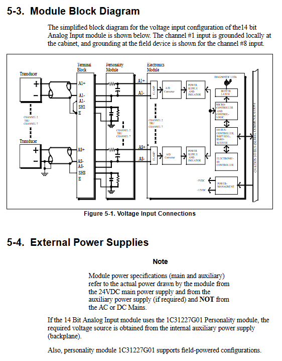
1) Analog input AI
13bit: 8 channels, ± 20mV~± 10V, 4~20mA, sampling 10 times/second
14bit: 8 channels, ± 1V, 4-20mA, sampling 20 times/second
High speed AI: 14bit, 50/60 times/second, supports thermocouple cold end compensation
Common features: accuracy ± 0.1%, wire breakage/fuse detection, common mode suppression 120dB
2) Analog output AO
Channel: 4 channels, 12 bits
Range: 0~5V/0~10V/0~20mA/4~20mA
Refresh: ≤ 2ms, supports overcurrent/undercurrent diagnosis
3) Contact input CI
Channel: 16 channels, onboard 48V wetting voltage
Douyin:<3ms reject,>7ms confirm
Diagnosis: Ground fault detection (<5k Ω)
4) Digital input DI
Voltage: 24/48V, 125V AC/DC
Structure: Single ended/differential optional
Protection: Surge suppression, fuse monitoring
5) Digital output DO&relay output
DO: 16 channels, 0~60V, 500mA/point
Relays: G2R (16 channels), KUEP (12 channels), supporting panel expansion
6) Specialized module
HART AI/AO: 8 channels, compatible with HART protocol
RTD: 4-channel, 3/4-wire system
SOE: 16 channels, timestamp 125 μ s
Servo/valve positioning: turbine, valve closed-loop control
Address and Register Rules
Fixed address space
16 addresses per module
D (13): Configuration/Main Status
E (14): Extended Configuration
C (12): Point quality fault
General configuration bit
Bit0: Module configuration (1=already configured)
Bit1: Force Error
Bit8: 50/60Hz selection
Bit15: Total number of point faults
Local and remote I/O
Local I/O
Controller direct connection, PCQL/PCRL card
Maximum 128 modules
Remote I
PCRR+MAU+RNC architecture
Fiber optic transmission, up to kilometer level
Maximum 1024 modules
Key questions and answers
Question 1: What is the general diagnostic mechanism for Ovation I/O modules? How to quickly locate faults?
answer
Diagnosis is achieved through dual implementation of LED and status register:
Green light: abnormal power supply
C green light: communication interruption
E Red light: External fault (grounding, fuse, sensor disconnection)
Red light: Internal malfunction (hardware, calibration, uncalibrated)
Quick positioning: First look at the LED → read the D register (address 13) again → finally check for the C register bit fault.
Question 2: What are the core differences between the 13 bit, 14 bit, and high-speed types of analog input AI modules? What scenarios are applicable to each?
answer
table
Type Resolution Sampling Rate Applicable Scenarios
13 bit AI 13 bit 10 times/second regular temperature, pressure, flow rate
14 bit AI 14 bit 20 times/second high-precision analog quantity
High speed AI 14 bit 50/60 times/second fast changing signal, dynamic acquisition
Commonality: All support * * ± 0.1% accuracy, 1000V isolation, and disconnection diagnosis * *.
Question 3: What impact will a ground fault in the contact input CI module have? How to avoid and detect?
answer
Impact: Single point grounding does not report errors; Multiple grounding points can cause signal misjudgment (open circuit showing closed).
Detection: The module has built-in * *<5k Ω grounding detection * *, with the E red light on and the D register Bit10 set.
Avoid:
Circuit grounding is prohibited
Use shielded wire for single ended grounding
Ensure cable insulation and reduce leakage current.