MITSUBISHI MELSEC A series PLC(MELSEC-A)
Scope of application and core positioning
Applicable Models
CPU:A1S(S1)、A1SC24‑R2、A2S(S1)、A1SH、A2SHCPU(S1)、A2ASCPU(S1/S30/S60)
Base, power supply I/O、 Full range of AnS modules for communication, positioning, etc
positioning
Authoritative manual for hardware installation, wiring, safety, maintenance, and fault codes
Targeting professional electrical personnel, emphasizing personal safety and equipment reliability
Safety precautions (highest priority)
Danger level (DANGER)
An external safety circuit must be established (emergency stop, limit, forward and reverse interlock)
The installation wiring must be completely powered off, and touching the terminals with electricity is strictly prohibited
The battery is not rechargeable/disassembled/heated/short circuited, only A6BAT is used
Output fault may remain on/off, critical outputs require external monitoring
Attention level (CAUTION)
Distance between signal line and power line * * ≥ 100mm * *, anti noise interference
Terminal screw torque 59~88N · cm, anti loosening/short circuit
No modification, opening, or parallel connection of power modules allowed
Module core specifications
1. Power module (key parameters)
Model input voltage output fuse/protection
A1S61P 100/200VAC 5VDC 5A overcurrent/overvoltage
A1S62P 100/200VAC 5V 3A+24V 0.6A overcurrent/overvoltage
A1S63P 24VDC 5V 5.5A overcurrent/overvoltage
A1S61PN 100~240VAC 5VDC 5A CE certification
2. Input module
Type: AC input, DC input, high-speed DC input
Points: 16/32/64 points, grouped and isolated in common ground
Response: High speed 0.1ms, normal 10-30ms
Voltage resistance: 500~1500VAC isolation
3. Output module
Type represents model, current response
Relay A1SY10 2A/point 10ms
Controllable silicon A1SY22 0.6A/point 1ms
Transistor A1SY40 0.1~2A/point 0.5~2ms
4. Hybrid I/O modules
A1SH42:32 input+32 output, DC transistor high-speed type
A1SX48Y18: 8 inputs+8 outputs, relay output
Installation specifications
Environmental Requirements
Temperature: 0~55 ℃, humidity: 10~90% RH
Altitude: ≤ 2000m, pollution level 2
Mechanical Installation
Vertical installation, with a distance of ≥ 30mm between the top and bottom to ensure heat dissipation
DIN rail: TH35-7.5, screw spacing ≤ 200mm
The module buckle is in place, and the torque of the fixing screw is 78~118N · cm
EMC and LVD compliance
Control cabinet metal grounding, cabinet door low impedance connection
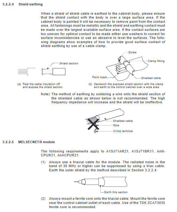
Large area grounding of shielding layer, non single spot welding wire
Add a noise filter to the power inlet and separate the input and output wiring
Wiring specifications
Grounding requirements
LG/FG must be grounded with wire diameter ≥ 2mm ² and length ≤ 30cm
Separation of strong and weak electricity, single end grounding of shielded cables
Power on sequence (mandatory)
Power on the PLC host
Power on external load power supply
Turn on the start switch
Prevent momentary erroneous output.
I/O wiring
AC input/output: withstand voltage 1500~2830VAC
DC input/output: 500VAC isolated
Public end grouping, prohibit cross group mixing
Fault safety design (must be implemented)
External safety circuit
Emergency stop, hardware limit, forward and reverse interlock
Output overload external fuse protection
CPU exception handling
Watchdog timeout, CPU failure: all outputs turned off
Communication failure: Remote I/O output turned off or maintained
Maintenance and upkeep
routine inspection
Module fixation, terminal fastening, and LED status are normal
Environment free of dust and corrosive gases
Regular inspection (6-12 months)
Voltage measurement, grounding resistance, insulation status
Battery replacement (low voltage alarm M9006/M9007)
Battery Specifications
Model: A6BAT, saving program and power down data
Error Code and Handling (Core)
Common high priority errors
10: Instruction error → Program instruction illegal
11: Parameter error → Parameter damage or configuration exception
20: RAM error → Memory hardware failure
22: WDT error → scan timeout, dead loop
31: I/O verification error → module missing/model mismatch
32: Output blown → Load short circuit or fuse broken
70: Battery error → low voltage or not connected
Key questions and answers
Question 1: Why is it necessary to build an external safety circuit for Mitsubishi A-series PLC? What specific tasks need to be done?
answer
Due to CPU failure, output breakdown, and communication abnormalities, PLC may mistakenly output or fail to shut down, which can cause personal injury and equipment damage.
Must be built:
Emergency stop circuit, upper and lower limits of travel, forward and reverse interlock
Key output external monitoring and circuit breaker protection
Power on sequence and power interlock circuit
Question 2: What are the three mandatory rules that must be followed for EMC anti-interference in the installation and wiring of A-series PLCs?
answer
The distance between the signal line and the power line is ≥ 100mm, and parallel bundling is prohibited
Shielded cable with large-area metal grounding, without using single thin wire welding
The power inlet is equipped with a noise filter, and the cables on both sides of the input and output are completely separated
Question 3: What is the reason for the WDT error (code 22) reported by the A-series PLC? How to quickly investigate?
answer
Reason: The program scanning time exceeds the watchdog limit time, which is commonly caused by program dead loops, excessive computation, and transient power outage interference.
Troubleshooting steps:
Check if the program has a dead loop/FOR NEXT mismatch
Split the process using CJ instructions to shorten scanning time
Check for power fluctuations and confirm if the D9005 monitoring voltage is normal