ADLINK cPCI-6965 series 6U CPCI single board computer
Overall product positioning and product line division
CPCI-6965 is a 6U CompactPCI industrial control board based on Intel mobile platform, with three hardware options: single slot (4HP) and dual slot (8HP). It is equipped with multiple rear adapter modules RTM and is designed for measurement and control, military, and automation CPCI chassis systems
1. Three types of SBC motherboards for differentiation
|Model | Slot Width | Core Differences|
|CPCI-6965 | 4HP (single slot) | Basic model, no PMC slot, streamlined panel I/O|
|CPCI-6965D | 8HP (dual slot) | with DB-6965PMC daughter card, supporting PMC expansion; Add PS/2 and parallel ports|
|CPCI-6965DZ | 8HP (dual slot) | with PMC, eliminating J3/J5 rear expansion connectors|
2. Four RTM adapter modules (supporting motherboard rear IO expansion)
-CPCI-R6000-965 (4HP): with SCSI, 2-channel USB, VGA, floppy drive SATA
-CPCI-R6000-L (4HP): No SCSI, the rest is the same as above
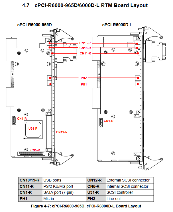
– cPCI-R6000-965D (8HP):4USB、PS/2、 Audio input and output SCSI
-CPCI-R6000D-L (8HP): No SCSI, the rest is the same as above
Hardware core specifications and platform architecture
1. Processor and chipset
-Choose between two CPUs: Intel Core2 Duo T7500(2.2GHz/4MB L2/TDP35W)、Intel Celeron M 550(2.0GHz/1MB L2/TDP27W), Passive heat dissipation;
-Chipset: Mobile GME965 North Bridge+ICH8M South Bridge; Integrated GMA X3100 graphics card, with a maximum shared memory of 384MB, supporting dual display output.
2. Memory and Storage
-Memory: Dual stack SO-DIMM, dual channel DDR2 533/667, maximum 4GB non ECC;
-Multiple storage options: onboard 2.5-inch SATA hard drive slot, Type II CompactFlash slot, optional onboard USB NAND flash module; Three SATA interfaces.
3. Bus specifications
-Front end bus FSB: 533/800MHz;
-CPCI bus: PICMG2.0 Rev3.0, hot swappable PICMG2.1 Rev2.0, 32bit/33MHz PCI;
-Expansion: Onboard 32bit/33MHz PMC expansion slot (D/DZ model); Two PCIe x1 Gigabit Intel 82573L Ethernet ports.
4. Electrical and Environmental
-Power supply: The whole machine is powered by CPCI 5V rail, providing DOS/Linux/XP no-load/full load power consumption (T7500 full load 47.08W, Celeron full load 32.67W);
-Temperature shock: working at 0-55 ℃ (forced 16CFM air cooling), storage at -40-85 ℃; Support industrial vibration and impact;
-Certified CE/FCC Class A.
Complete IO interfaces on the front and rear panels
1. Front panel of motherboard (distinguishing 4HP/8HP)
Universal interface (full series):
-Dual DVI (DVI-I+DVI-D, supports DVI+VGA, dual digital independent display, up to 2048 × 1536);
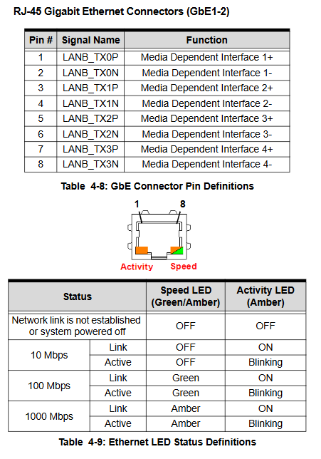
-Dual Gigabit RJ45 Ethernet ports (with speed/activity dual color LED);
-4-channel USB 2.0; 2-channel DB9 serial port (software switch RS232/422/485/485+);
-Status indicator lights: power green, hard drive red, watchdog amber, universal blue; Reset button.
8HP exclusive: PS/2 keyboard and mouse, 25 pin parallel port, PMC expansion panel.
2. RTM rear IO (chassis back expansion)
4HP model: VGA, 2xUSB, external SATA, floppy drive, 7-pin SATA;
8HP model: 4xUSB, VGA, PS/2, microphone/line output SCSI、 Soft drive SATA;
Equipped with LSI Ultra320 SCSI controller (RTM model with SCSI, supporting RAID1 mirroring).
3. Onboard expansion interface
CPCI backplane J1/J2/J3/J5 connectors, PMC slot, onboard USB flash socket, RTC button battery CR2032, watchdog WDT circuit, ITE IT8712F super IO (serial/parallel/hardware monitoring).
Detailed explanation of core functional modules
1. Display system
Sil1362 SDVO to DVI chip, dual independent display output, supports hot swapping DirectX9/OpenGL1.5。
2. Serial port function
Both COM1 and COM2 switch between four electrical modes (RS232 full modulation, 422 half duplex, 485 half duplex, 485+) through onboard DIP switching. The manual provides a complete configuration table for DIP switches SW1-SW8.
3. PMC Expansion
3.3V/5V IO level optional (JPX1 jumper), matched with DB-6965PMC adapter card to achieve front PMC panel output.
4. Watchdog Timer WDT
Implemented by SuperIO hardware, timeout range is 1 second to 255 minutes; The software can start stop, reload timing, and automatically reset the entire machine after timeout; Comes with DOS sample C source code.
5. PXE network boot
The dual gigabit network card supports remote network booting and requires a DHCP/MTTFP/PCIe server.
6. Hardware monitoring
Real time collection of CPU/board temperature and various voltages, which can be viewed in the BIOS for status.
Installation chapter
Step by step complete installation process, accompanied by physical pictures:
1. CPU cooling: Pre installed at the factory, not recommended to be disassembled, replacement requires matching thermal pads;
2. Installation of memory SO-DIMM;
3. CompactFlash card fixation (with metal blocking plate to prevent loosening);
4. 2.5-inch SATA hard drive: DB-6910SAT adapter board, fixed with column screws;
5. PMC sub card assembly (switch 3.3V/5V positioning key);
6. Installation of onboard USB flash module;
7. Insert the motherboard into the CPCI chassis and lock it tightly;
8. Install the RTM adapter module (must match the model to avoid hardware damage).
Driver installation
Supported systems: Windows XP/Vista, Fedora7/10, can provide Linux/VxWorks BSP;
Windows XP installation sequence: chipset driver → graphics card driver → network card driver → SCSI driver (RTM requires installation with SCSI); The driver can be downloaded from the official website of the accompanying AD integrated CD.
AMIBIOS8 Configuration Manual
1. Entry method: Press Del when starting up; Global hotkey F1 Help, F8 Fault Default, F9 Optimal Default, F10 Save Exit, ESC Abandon;
2. Eight major settings main menu:
-Main: System time and date;
-Advanced: CPU virtualization/multi-core/energy-saving IDE/SATA、 Soft drive, SuperIO serial parallel port, hardware temperature monitoring, serial remote console, USB configuration;
-PCI/PnP: IRQ/DMA resource reservation;
-Boot: device priority, fast boot, and PCIe network boot;
-Security: administrator/user two-level startup password;
-Chip: Number of USB ports, HD audio, network card PXE switch;
-Exit: Save/Discard loading default parameters.
Hardware drawings and pin definitions
1. Board PCB layout diagram (4HP/8HP front and back assembly diagram), indicating CPU, north-south bridge, network control SODIMM、 Various types of connectors;
2. Front and rear panel IO schematic diagram;
3. Complete pin list for all connectors: USB, PS/2, DVI-I/DVI-D, DB9 serial port, parallel port, RJ45, SATA, CF, PMC, CPCI J1/J2/J3/J5 backplane pins;
4. Switch jumper: CMOS clear button, PMC IO level jumper, serial mode dial code table.