ADLINK cPCI-6860A 6U CompactPCI dual core single board computer
Chapter 1 Product Overview and Complete Specifications
product positioning
Standard 6U 8HP dual slot CompactPCI controller, following PICMG2.0R3.0 hot swappable, PICMG2.16 packet switched backplane, and PICMG2.9 IPMI management specifications; Targeting telecommunications data centers, servers, and network equipment, it supports single/dual Xeon processors, with front and rear dual I/O separation design, and is paired with RTM to expand massive storage and network ports.
Core hardware platform (cPCI-6860A motherboard)
(1) Processor
Dual FC-MPGA604 CPU slots, supporting two configurations:
Single CPU: Only install CPU1 slot (CPU0 is empty and unavailable), Xeon 1.8/2.0/2.2/2.4/2.8GHz (400FSB), 3.06GHz (533FSB), 512KB L2 cache
Dual CPU: Two low voltage Xeon 1.6/2.0GHz of the same model. Mixing different CPUs is prohibited to avoid overheating and damage
(2) Chipset architecture
Intel E7501 MCH memory bridge+ICH3-S southbridge+P64H2 64 bit PCI-X bridge; Onboard ATi Rage XL discrete graphics card (8MB video memory) Winbond W83627 SuperIO。
(3) Memory
2-channel 72 bit ECC registered DDR DIMM slots, standard maximum 4GB; OEM customized 4-slot version can be expanded to 8GB; memory must be installed in pairs with DDR200/266 PC1600 of the same capacity and specifications.
(4) BIOS Features
Phoenix/Ward enhances BIOS, supports PXE diskless, WFM remote management, USB device boot, CMOS data EEPROM backup, COM1 serial port remote console, BIOS write protection antivirus, and custom boot logo.
(5) Network resources (switchable before and after)
Front panel: 1 100Mbps 82562EM Ethernet port+2 Gigabit 82546EB Ethernet ports
The RTM adapter board can be extended by an additional 2 channels of gigabit, with a maximum of 4 gigabit for the entire machine; Gigabit can switch between front panel/PICMG2.16 backplane/RTM rear panel through dial-up, and cannot output multiple channels simultaneously
All network ports support automatic negotiation, 802.3x traffic control, and link/rate indicator lights
(6) Display, serial port USB、PS/2
VGA: Front and rear dual DB15, up to 1280 × 1024 24 bit color
Serial port: Front COM1 (DB9, 2KV ESD protection); RTM exports COM2 and IPMI management serial port MGMT
USB: Front 2 x USB 1.1; RTM rear 2 x USB 1.1, single port 500mA overcurrent protection
PS/2 keyboard and mouse: front Y-shaped interface, RTM independent keyboard and mouse pin
(7) Storage (motherboard only leads out channels, all devices are in RTM)
Two ATA100 IDE channels, RTM provides: 40 pin standard IDE, 44 pin 2.5-inch laptop IDE, Type-II CompactFlash card slot, supporting DOM electronic disk, CF card, 2.5-inch SSD/mechanical disk.
(8) RTM exclusive extension (motherboard does not have this hardware)
Ultra320 LVD SCSI controller (LSI 53C1020R, up to 320MB/s), additional 2 Gigabit Ethernet ports, floppy drive 34 pin interface.
(9) Hardware monitoring and watchdog
W82782 monitoring chip: CPU temperature, board temperature, fan speed, and various voltage acquisition; Programmable watchdog with 1-255 seconds/minute, timeout reset, compatible with DOS/Windows development library.
(10) Optional BMC substrate management card
Supports PICMG2.9 and IPMI v1.0 out of band remote management, and can still read hardware status, power on/off, and SEL event logs through the serial port during power outages/crashes.
Environmental and power consumption parameters
Environment: Working at 0-50 ℃ (forced 50CFM air cooling), storage at -20~80 ℃; No condensation humidity 5%~95; Through HALT high and low temperature vibration aging test
Power consumption reference:
Single Xeon 2.0G+2GB+4 Ethernet ports: 107W
Dual low voltage Xeon 1.6G+2GB+4 network ports: 99.6W
Dual low voltage Xeon 2.0G+2GB+4 network ports: 124W
Onboard LED indicator light (front panel)
Green power light: always on when powered on
Red IDE read-write light: Storage access flashing
Yellow WDT light: Watch dog enabled flashing, always on after timeout
Blue hot swappable light: Always on when power is off and the card can be unplugged
Chapter 2: Connectors, Jumpers, and Board Layout
CPCI-6860A motherboard hardware layout
Onboard resources: dual CPU slots, dual DDR memory slots, lithium batteries, CompactPCI J1/J2/J3/J4 backplane gold fingers, single Clear CMOS jumper JPX1
Front panel exposed interfaces: COM1 DB9, VGA DB15, dual USB, PS/2 composite port, 3 network ports RJ45, reset button, status LED
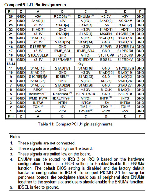
CompactPCI bus definition: Complete list of all pin signals for J1 (64 bit PCI), J2 expansion, J3/RTM local IO, and J4 management bus
Key jumpers and dialing codes
JPX1 Clear CMOS: 1-2 defaults to normal; Power outage shortened by 2-3, clearing BIOS time and settings
RTM dip switch:
Gigabit LAN1/LAN2 four group dialing: switch output to backplane PICMG2.16 or rear RTM (factory default rear)
SWXI VGA DIP: Control Rear VGA Enable/Disable
RTM IDE master-slave jumper: CF card can be set as master/slave
CPCI-R6860A adapter board interface
Rear all export storage and expansion IO, including:
PS/keyboard, PS/mouse independent interface
VGA DB15, COM2, MGMT management serial port, rear dual USB
2-channel Gigabit RJ45, Ultra320 68 pin SCSI
40 pin main IDE, 40 pin secondary IDE, 44 pin 2.5-inch IDE, CF card slot, 34 pin floppy drive
Provide complete pin definition drawings for SCSI, IDE, floppy drive, and PS/2.
Chapter 3 Hardware Step by Step Installation
Full process anti-static operation, installation sequence: CPU → BMC (optional) → heat dissipation module → memory → RTM storage medium
CPU installation
Single CPU: only inserted into CPU1 slot, CPU0 installation prohibited; Align the CPU triangle mark with the slot positioning angle and prohibit violent pressing
Dual CPU: Two low-voltage Xeons of the same model, and both cooling fans must be fully assembled
BMC card installation: Install BMC when there is no heat dissipation, align it with the dedicated slot on the motherboard and press it tightly, then assemble the heat dissipation
Assembly of heat dissipation module
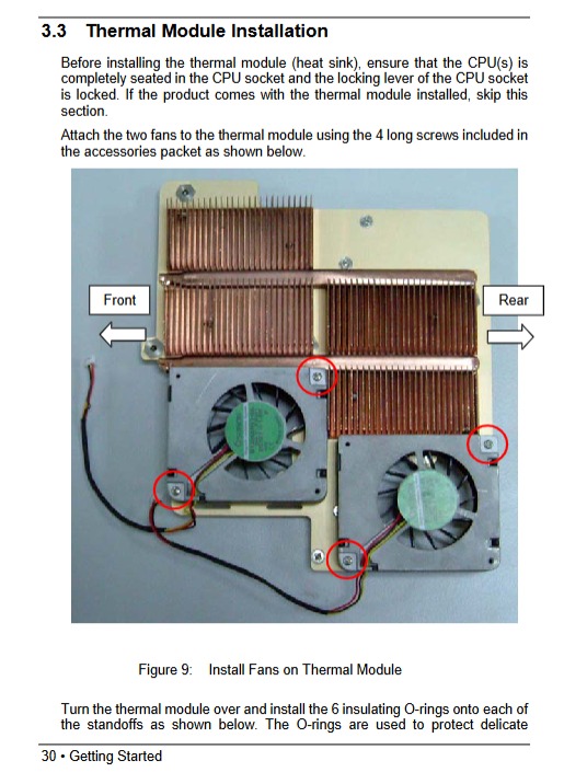
First, fix the dual fans on the copper heat dissipation fins and cover them with insulating O-rings to prevent damage to the PCB components
The overall fit of the CPU core is secured with 6 screws at the bottom. The fan power cord is connected to the motherboard fan socket, and the wiring harness is fixed with zip ties to prevent insertion, removal, and scratching
Memory installation: paired ECC DDR with the same capacity, slot buckle with aligned notches, single/different capacity cannot boot up
RTM storage installation
2.5-inch IDE hard drive: Remove the RTM bracket to secure the hard drive, and connect the 44 pin ribbon cable
CF card: direct rear plug-in, jumper setting IDE master-slave
RTM disassembly and assembly precautions: The ADLINK 6400 chassis needs to have its top cover removed to prevent cable compression from damaging the connectors; The motherboard and RTM must be used together, mixing them will burn the hardware
I/O wiring rules: The same device (VGA/Ethernet/keyboard/mouse) cannot be connected to both front and rear interfaces at the same time
Chapter 4 Equipment Driver Installation Guide
Supporting operating systems
Windows 98/NT/2000/XP、RedHat Linux7~9; The driver is unified in the matching All in One CD
Standard installation sequence (Win2000/XP)
Intel E7501 chipset INF driver (basic bus recognition)
ATI Rage XL VGA graphics card driver
82562/82546 Gigabit/100Mbps Network Card Driver
LSI Ultra320 SCSI driver (only installed with RTM)
Key points of installation steps
Close all background programs before installation and run Setup with administrator privileges
The SCSI driver XP comes with a simplified version, and it is recommended to use the original CD driver to improve compatibility
After installing each type of driver, restart the system according to the prompts
Appendix A IPMI v1.0 Function List
Optional BMC card for out of band hardware management, supporting functions: machine cold/hot restart, reading chassis status, hardware sensor (SDR) collection, fault event log (SEL) reading, FRU hardware information reading, remote serial port console; SEL logs do not support random read and write, SDR sensor data is read-only.