ADLINK cPCI-6910 series 6U CompactPCI single board computer
Chapter 1 Product Introduction (Product Positioning, Model, Hardware Block Diagram, Packaging)
product positioning
Single slot 4HP standard 6U cPCI controller, equipped with dual core low-power Xeon LV/ULV 65nm processor, using Intel E7520 server level chipset, supporting PCIe high-speed bus, four gigabit network, multi type storage, compatible with system slot/peripheral slot, supporting hot plugging, matched with two RTM rear IO expansion cards, suitable for telecommunications switches, military measurement and control, and server blade devices.
Differentiation of hardware models across the entire series
Motherboard model (distinguishing between CPU and onboard memory)
CPCI-6910/DCX20/M1G: LV 2.0GHz dual core Xeon, 1GB soldered ECC DDR2
CPCI-6910/DCX20/M2G: LV 2.0GHz dual core Xeon, 2GB soldered ECC DDR2
CPCI-6910/DCX16/M1G: ULV 1.66GHz dual core Xeon, 1GB memory
CPCI-6910/DCX16/M2G: ULV 1.66GHz dual core Xeon, 2GB memory
CPCI-6910/DXL16/M1G: LV 1.66GHz dual core Xeon, 1GB memory
CPCI-6910/DXL16/M2G: LV 1.66GHz dual core Xeon, 2GB memory
Differences between two RTM rear adapter plates
CPCI-R6910: Equipped with LSI SAS controller, supports SAS/SATA hard drives, without SCSI
CPCI-R6911: Equipped with LSI Ultra320 SCSI controller, supporting RAID0/1 array, and equipped with 68 pin SCSI interface
Factory packaging accessories
Motherboard kit: cPCI-6910 body, CPU heat dissipation kit, SATA/IDE/CF adapter card, PS/2 one/two wire, RJ45 to DB9 serial cable, driver CD, paper manual
RTM kit: corresponding adapter board body, supporting storage cables (SAS/SATA/CSIS), hard disk mounting bracket
Optional: CF card adapter module, additional storage daughter card
Basic Core Highlights
Single channel dual core low-power Xeon, 667MHz front-end bus, 2MB on-chip L2 cache
ECC soldered DDR2 memory, up to 2GB, hardware data correction
4-port Gigabit Ethernet (front 2+back 2, PCIe x4 channels), supporting PICMG2.16 packet switching backplane
Onboard PMC expansion slot, dual serial ports, 4-channel USB 2.0, VGA display
Multi storage compatibility: IDE/SATA/CF; RTM optional SAS/Ultrara320 SCSI array
Integrated IPMI v1.5 substrate management, two-level hardware watchdog, hardware voltage and temperature monitoring
Full PICMG standard compatibility: 2.0 hot swappable, 2.16 packet switching, 2.9 IPMI management bus
Chapter 2: Complete Hardware Specifications and Power Consumption Data
CPCI-6910 motherboard core specifications
Mechanical standard: 6U 4HP cPCI, size 233.35 × 160mm; supports chassis hot plugging, front pop-up handle controls power on enumeration signal
CPU: 478 pin micro FCPGA slot, single core Xeon LV/ULV (1.66/2.0GHz), 65nm process, CMP dual core architecture, intelligent power regulation
Chipset: Intel E7520 Northbridge+6300ESB Southbridge, supports PCIe x8 split multiplexing x4, HI1.5 high-speed bridging bus
Memory: Onboard soldered dual channel 72 bit ECC DDR2 400, fixed 1/2GB, hardware SEC/DED memory error correction, supports memory mirroring
Graphics: ATI ES1000 2D graphics card, PCI 32-bit bus, up to 24 bit color, industrial stable output
Network: Dual Intel 82571EB Gigabit Controller, PCIe x4, A total of 4 gigabit channels (front 2, RTM rear 2), with the ability to switch between backplane PICMG2.16 or rear RJ45 via dial-up
Storage Controller
Nanqiao Integrated Dual UltraATA10 IDE Channels (Mainboard Main Channel, RTM Sub Channel)
Two onboard SATA ports, led out to RTM through J3 backplane
Peripheral bus
4-channel USB 2.0 (front 2, rear 2), EHCI+UHCI dual controllers, supporting USB device boot
Two 16550 compatible serial ports: COM1 front, COM2 rear RTM, SWZ2 dial-up switch serial/IPMI management mode
PMC 64bit/66MHz expansion slot (J4 backplane)
PLX PCI-6540 PCI-X bridge, supporting transparent/non transparent working modes, can be used as an independent intelligent subsystem
BIOS:4MB Phoenix-Award Flash, Write protection switch, supports USB boot, PXE diskless, serial remote console, SpeedStep energy-saving
IPMI BMC: ATmega128L management chip, IPMI v1.5, Independent 128KB firmware Flash, capable of reading hardware sensors and remote power on/off when powered off
Environment and Certification: Work requires 30CFM forced air cooling, CE/FCC A-level industrial certification
Comparison of two RTM adapter board specifications
Parameter cPCI-R6910 cPCI-R6911
Storage controller LSI SAS1064E LSI Ultra320 SCSI 53C1020
The array supports SAS pass through, no hardware RAID RAID0 stripe/RAID1 mirroring
Rear interface COM2, 2USB2.0, 2 Gigabit RJ45, CF, SAS/SATA COM2, 2USB2.0, 2 Gigabit RJ45, CF, 40pin IDE, 68 pin SCSI
Backplane channel RJ3/RJ4/RJ5 cPCI standard connector RJ3/RJ4/RJ5 cPCI standard connector
IO Resource Comparison Table
Distinguish between motherboard front end, motherboard onboard, two RTM rear end/onboard all serial ports USB、 Network port, storage, PMC, VGA resources, clearly distinguish detachable daughter card interfaces.
Tested power consumption under different operating conditions (ULV1.66/LV1.66/LV2.0 CPUs)
Test environment: 2GB ECC memory, SATA 80GB hard drive, 350W industrial power supply
DOS standby: ULV minimum 27.5W, LV2.0 maximum 33.5W
Linux standby: range of 24.8~27.6W
Windows XP full load (100% CPU): 39.5W~48.5W
Windows XP idle: 24.5~26W
Provide current and power details by dividing the voltage into two channels, 3.3V/5V.
Chapter 3: In Depth Explanation of Hardware Functions
Disassemble the motherboard chip and peripherals module by module. Working principle:
Processor: Dual core CMP architecture, prefetching mechanism, dynamic power throttling, SpeedStep energy-saving
E7520 North Bridge: Three PCIe x8 channels, can be split into multiple x4, DDR2 memory controller, ODT on-chip termination, hardware memory failure redundancy
6300ESB South Bridge: Integrated SATA/IDE/USB/serial port/two-level watchdog/ACPI/APIC interrupt, SMBus management bus
PCIe bus: bidirectional 5Gbps bandwidth per channel, hardware hot plugging, CRC link verification, automatic link retraining
Storage system: UltraATA10 dual IDE, SATA1.5G, distinguishing between motherboard local storage and RTM extended storage
USB 2.0 EHCI high-speed+UHCI low-speed, supports USB keyboard and mouse boot under DOS/BIOS, overcurrent detection
UART serial port: standard 16550, hardware flow control, COM2 can be reused as IPMI management serial port
Two level watchdog WDT (integrated in 6300ESB)
Two stage countdown: In the first stage, an IRQ interrupt is triggered when the timeout occurs, and in the second stage, the hardware is reset when the timeout occurs
Timing accuracy in two levels: 1 μ s~1s/1ms~10min; Support free running mode
Supporting GPIO control WDT alarm indicator light, system reset pin
ATI ES1000 graphics card: pure 2D industrial acceleration, compatible with servers without displays, remote serial port operation and maintenance
PLX PCI-X bridge: dual-mode switching, system slot transparent bridge, peripheral slot non transparent independent bus isolation
Hardware monitoring IT8712F: Real time collection of CPU/motherboard temperature, 3.3V/5V/12V voltage, threshold alarm
Chapter 4: Full Definition of Connectors, Layout, and DIP Switches
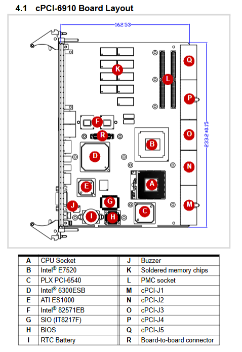
Overall layout of motherboard
Label the positions of CPU, E7520 North Bridge, 6300ESB South Bridge, ATI graphics card, PMC slot, memory array, J1-J5 cPCI backplane gold finger, and all components on the front panel.
Front panel IO and status LED
Exposed interfaces: VGA, PS/2 composite port COM1、 Dual USB, 2 Gigabit RJ45, reset button
Definition of indicator lights: power yellow light, hard disk read/write red light, watchdog amber alarm light, hot swappable blue ready light
Removable storage daughter card
DB-6910IDE (2.5-inch IDE), DB-6910SAT (SATA), DB-6910CF (CF card) three adapter board drawings, board to board connector pins.
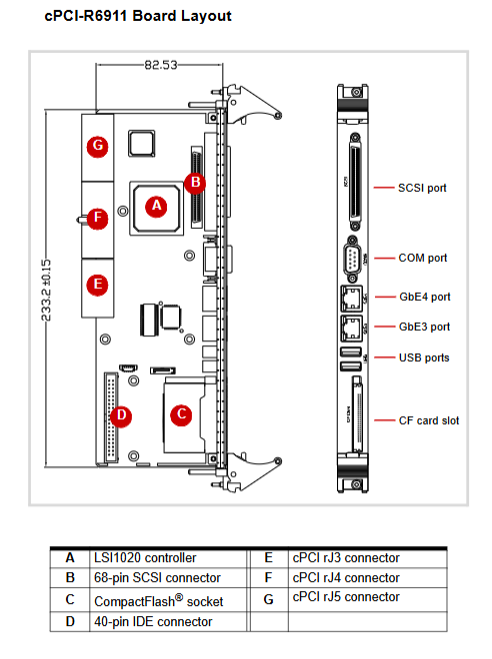
R6910/R6911 adapter board layout
Display two RTM onboard SAS/CSIS controllers CF、IDE、 Board to board backplane connectors, rear panel serial/USB/Ethernet/SCSI/SAS interface drawings.
Standard definition of all interface pins
Complete list of USB, RJ45 Gigabit Ethernet, VGA DB15, PS/2, COM DB9, CF card, SATA/SAS board to board connector, cPCI J1/J2/J3/J4/J5 five groups of backplane gold finger all pin signal, power, and ground allocation.
Dial switch function (core configuration switch)
SWZ1: Clear CMOS button, power off and press to reset BIOS
SWZ2: 4-digit dialing, switch between COM2 normal serial port/IPMI management serial port (factory default COM mode)
SW1 motherboard 4-digit debugging switch: distinguish between B2 old version/B3 new version PCB definitions, control pre charging, system slot identification, and debugging functions
RTM side SWY series dial-up (R6910/SWZ; R6911/SWY): controls whether the rear gigabit network is connected to the backplane PICMG2.16 or the rear RJ45, all ON enable the rear network port, all OFF go to the backplane
R6911 SWY5: Set CF card IDE master/slave mode
Chapter 5 Hardware Step by Step Installation Tutorial (Anti static Mandatory Pre installation)
Pre specification: Full process anti-static wristband, anti-static workbench, prohibit bare hands from touching the chip slot
Installation tools: Phillips/Phillips screwdriver, hexagonal socket (hard drive bracket)
CPU installation steps
Rotate to unlock the slot lock, lift the pressure plate, and remove the protective cover
Align the CPU triangle positioning mark with the slot and place it flat without pressing
Buckle the pressure plate and secure it with locking screws
Installation of heat dissipation module
Tear off the CPU/Northbridge thermal protection film
Align the radiator with the positioning column and tighten the four screws diagonally in steps to ensure that the thermal pad is fully attached
Storage device installation (motherboard/RTM dual path)
Local 2.5-inch IDE/SATA hard drive on motherboard: Install copper pillar → Secure adapter card → Vertical buckle board to board connector screw locking
RTM side SAS/SATA hard drive: equipped with SAS daughter card assembly and bracket fixation
CF card module: Install CF adapter board, protective bracket, vertically plug and fix
Plug and install the entire machine chassis
Release the up and down pop-up handles, align with the chassis rails, and push in the board
Tighten the handle to lock it in place, and tighten the panel fixing screws
The RTM adapter board is installed from the back of the chassis using the same process
Chapter 6 Driver Installation Guide
Supporting operating systems
Windows 2000/XP/Server 2003, RedHat/Fedora Linux, VxWorks (BSP requested separately)
Standard driver installation sequence (with accompanying All in One CD)
Intel E7520 chipset INF bus driver
ATI ES1000 graphics card driver (divided into Win2000/XP step-by-step graphic and text operations)
82571EB Gigabit Network Card Driver
SAS driver (R6910 only)
Ultra320 SCSI driver (R6911 only)
Detailed operation of graphics card installation: Device Manager updates drivers, specifies the INF path of the CD, restarts and takes effect. Complete steps screenshot instructions
Chapter 7 Complete Development Materials for Two Level Watchdog WDT
WDT hardware block diagram
Integrated into 6300ESB South Bridge, 35 bit 32-bit down counter, two-level preloading registers, interrupt/reset control logic
Complete Register Description
BAR base address, two-level preload register, interrupt status, reload register, mode latch register, specify register unlock and write fixed instruction sequence
Work Mode
Standard watchdog mode: Level 1 timeout IRQ, Level 2 hardware reset
Free running mode: single-stage only, loop flipping WDT_TOUT output pin
Programming Standard Process
BIOS enables WDT → Reuse pins for WDT function → Configure frequency division and interrupt types → Write timer values → Enable timer, timed reload feeding dog to prevent reset
Supporting tools: HRWDT.EXE debugging tool under DOS, with sample source code attached on the CD; Simultaneously introduce the configuration conditions for PCIe diskless network boot
Chapter 8 Phoenix Ward BIOS Full Menu Detailed Explanation
Press Del/Tab to enter the settings when booting up. The complete nine main menus provide detailed descriptions of each function, option, and parameter, along with a screenshot of the BIOS interface
Standard CMOS standard settings: system time, IDE hard disk auto detection, memory information, boot error strategy
Advanced BIOS settings: CPU cache, power on self-test, boot sequence NumLock、 Serial port remote console (VT100/ANSI baud rate configuration), power on password mode
Advanced Chipset chipset settings: BIOS cache, memory ECC mode, CPU temperature control delay
Integrated Peripherals: IDE/SATA mode, USB controller, serial IO address, watchdog switch, PCIe network card boot ROM
PnP/PCI plug and play: IRQ resource automatic/manual allocation, PCI graphics card palette
Frequency and voltage control: Spread spectrum clock switch
Load default/optimize default parameters for faults
Administrator/User Level Startup Password Settings
Save exit/abandon exit operation
Chapter 9 IPMI v1.5 Substrate Management Interface (Remote Operation and Maintenance Core)
Target audience: IPMI protocol development, remote operation and maintenance engineers in computer rooms
Standard BMR-AVR-cPCI instruction set
Complete table listing of IPMI standard required/optional instructions: device recognition, hot/cold reset, watchdog control, sensor reading, FRU hardware information, event log SEL read/write
Linghua OEM Extended Exclusive Command (Factory Specific)
10 dedicated instructions, supporting firmware version query, remote power on/off, motherboard hard reset, SMBus bus switch, hardware address reading, debugging variable output, each with a complete byte protocol table for sending and receiving
CPCI Backplane IPMB Address Mapping Table
IPMB communication address corresponding to different slots of the chassis (slot codes 0-31)
Hardware Sensor List
Distinguish between B2 old PCB and B3 new PCB sensor items: 3.3V/5V/12V voltage, CPU/motherboard temperature, BMC watchdog, power failure detection
BMC firmware version iteration history, known defects
Defect: BMC does not have an independent RTC, and the internal time is reset to zero after the whole machine is powered off; SDR sensor logs are stored in Flash and cannot be randomly modified
Appendix: Complete Configuration Tutorial for Serial Remote Console
Without the need for a monitor or keyboard, use Windows Hyperterminal to view POST, operate BIOS and system through a cross serial cable:
Hardware: Definition diagram of null modem cross serial cable connection
Windows HyperTerminal installation, new connection, baud rate matching (9600/115200, etc.), terminal simulation ANSI settings complete set of graphic and textual steps
The BIOS should enable the Console redirection remote redirection switch, and the baud rates on both ends must be consistent