ADLINK NuPRO-900A PICMG 1.2 ePCI-X Dual Xeon Industrial System Motherboard (SHB)
Chapter 1 Product Introduction (Hardware Platform Core Parameters)
1.1 Mechanical standards
Full length PICMG1.2 ePCI-X specification, size 338.6mm × 122mm, compatible with standard full length industrial chassis, powered by backplane gold fingers and expansion bus.
1.2 Core Computing Platform
CPU: Dual FC-mPGA604 slots, supporting single/dual low-power Xeon processors, 400/533MHz front-end bus, maximum clock speed of 3.06GHz, 512KB on-chip L2 cache, supporting hyper threading DLurst architecture; Single CPU installation does not require terminal resistors, dual CPUs must be matched with the same model.
Three sets of chipset
MCH: Intel E7501 memory control hub, dual channel DDR memory, maximum 3.2GB/s memory bandwidth;
ICH3-S: Intel 82801CA input/output southbridge, integrated with dual IDE, USB1.1, SMBus, SuperIO bus;
P64H2: PCI-X bridge, providing two independent 64bit/133MHz PCI-X high-speed buses.
Memory: 4-channel 184 pin DDR DIMM slots, supporting ECC verification type registered DDR 200/266MHz; The memory must be installed in pairs, with a maximum total capacity of 8GB, and hardware ECC memory error correction to ensure server level data stability.
1.3 All onboard I/O hardware resources
1) Graphic display
ATI Rage XL discrete graphics card, onboard 8MB discrete graphics memory, DB15 VGA rear interface, up to 1600 × 1200@16bit Color output.
2) Network module
Dual Intel 82546EB Gigabit RJ45 Ethernet ports, equipped with PCI-X 133MHz bus, supporting 10/100/1000M adaptive, IEEE802.3x traffic control, and PCIe diskless network boot; Network port dual color indicator light: green=speed (on 1G/off 100M), yellow=link/data flashing.
3) Serial/Parallel Port
COM1 and COM2 RS232 (10 pin output, matched with DB9 board), standard 16550 UART, default address 3F8/2F8, IRQ4/IRQ;
IEEE1284 bidirectional parallel port (26 pin pin), BIOS can switch between Normal/EPP/ECP printing modes, default address is IRQ7.
4) Storage Controller
Dual Ultra ATA100 IDE channels (primary/secondary, each channel supports two hard drives);
34 pin standard floppy drive controller, onboard floppy drive pins;
Reserved Mini PCI expansion slot for external network card/storage daughter card.
5) USB and keyboard and mouse
Two USB 1.1 ports (onboard 10pin pin, 500mA single port overcurrent protection); PS/2 composite keyboard and mouse circular interface, paired with a Y-line to simultaneously connect keyboard and mouse.
6) Hardware monitoring and watchdog
Winbond W83627HF SuperIO+W82782 monitoring chip: real-time acquisition of CPU temperature, motherboard temperature, dual CPU fan speed, 3.3V/5V/12V voltage channels;
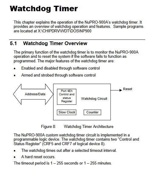
Onboard programmable two-level watchdog timer: timing range of 1-255 seconds/1-255 minutes, software feeding dog timeout triggers machine hard reset, register mark WDT reset record for easy fault tracing.
7) Chassis management pin
Chassis lid opening detection, front panel (power on/reset/power light/hard disk light/buzzer, keyboard lock), dual CPU 4-pin speed regulating fan socket.
1.4 Basic BIOS Features
Phoenix/Ward industrial BIOS, 4MB Flash, supports BIOS write protection antivirus, custom OEM boot logo, DMI hardware information, PXE network boot, boot password hierarchical management, press Del to enter the settings interface when booting.
1.5 System compatibility and environmental parameters
Operating systems: Windows 2000/XP, RedHat Linux, BSP can be requested for other embedded systems;
Working temperature range: 5~55 ℃, storage -40~70 ℃, humidity 5%~95%, no condensation;
Material: All onboard plastic components comply with UL94V flame retardant standards.
Chapter 2: Complete Definition of Connectors, Jumpers, and Pins
2.1 Overall layout of motherboard
The document provides a top view drawing of the motherboard, indicating all connector numbers: dual CPU slots, 4 DDR memory slots, dual IDE, floppy drive Mini PCI、VGA、 Dual network ports, COM/parallel/USB pins, fan socket, front panel, chassis cover opening detection, clear CMOS jumper JP2.
Rear panel IO: VGA DB15, dual RJ45 gigabit network, PS/2 composite port.
2.2 List of all interface pins (standardized definition one by one)
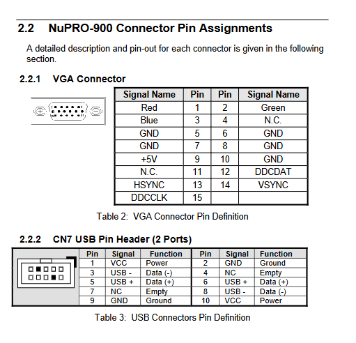
VGA DB15:RGB、 Field synchronization, DDC data clock, 5V power supply, complete grounding pins;
10 pin USB plug: Two USB differential data, power, ground;
COM serial port 10pin: DCD/RXD/TXD/DTR/DSR/RTS/CTS/RI standard modem full signal;
Gigabit RJ45: 8-channel differential transceiver, equipped with dual color light status instructions;
26 pin parallel port: complete 8-bit data, handshake, error, paper feed signal;
Chassis lid opening 2 minutes: switch detection+ground;
CPU fan 3pin: ground, 12V power supply, speed feedback;
PS/2 circular port: keyboard/mouse data clock, 5V power supply;
34 pin floppy drive industrial standard pin;
40pin ATA10 IDE main/secondary channel address, data, interrupt, reset;
Front panel 20 pin: power button, reset, power LED, hard disk LED, buzzer, keyboard lock, 5V standby;
Mini PCI 124 pin full pin: PCI bus, SMBus, AC audio, reset, clock, power.
2.3 Jumper Instructions
Only JP2 single channel clear CMOS jumper: After power failure, short-circuit the metal pin, clear the RTC clock and all BIOS settings, and restore factory parameters.
Chapter 3: Step by Step Tutorial for Hardware Installation
Pre anti-static mandatory specification
All disassembly and assembly must be carried out on an anti-static workbench and a grounded wristband. It is forbidden to touch the CPU and memory with bare hands, as static electricity can permanently damage the components.
3.1 CPU installation steps
Open the lock rod of mPGA604 slot, lift up the pressure plate, and remove the protective cover;
Align the CPU triangle positioning mark with the corner of the slot and place it flat without external pressure;
The clamping plate and locking rod make a clicking sound;
Apply thermal grease evenly to the CPU core, fix the original heat dissipation kit, and plug the fan into the corresponding FAN socket;
Both CPUs of the dual CPU model must be equipped with heat dissipation, otherwise they will overheat, crash, and burn out.
3.2 DDR Memory Installation Rules
The memory must be inserted in pairs of the same specifications, with priority given to filling the DM1/DM2 slots;
Open the buckles on both sides of the slot, align the memory gap with the slot partition, and press vertically to lock the buckles automatically;
Supports 64MB~2GB single ECC DDR, inconsistent capacity will prevent booting.
3.3 IDE hard drive wiring
Distinguish between primary/secondary IDE channels, align the 40pin pin1 red mark with the hard disk/motherboard pins, mount up to two hard disks per channel, and recognize disk parameters in BIOS.
3.4 Basic BIOS Operations
Press Del during the boot memory self-test phase to enter the settings; The configuration items are stored in the RTC battery powered CMOS and can be set with parameters such as startup sequence, hardware IO address, parallel port mode, watchdog switch, power management, etc. For detailed configuration, please refer to the driver and watchdog chapter.
3.5 Key points of operating system installation
BIOS adjusts the boot sequence (floppy drive/CD/hard drive/network);
Before installing the system, load the original chipset driver to avoid hardware abnormalities in PCI-X, graphics card, and network card;
It is recommended to close excess idle peripherals for industrial equipment to improve stability.
Chapter 4 Equipment Driver Installation Guide
The drivers are stored uniformly on the accompanying ADLINK All in One CD and only provide a complete installation process for Windows 2000/XP systems.
Standard installation sequence
Intel E7501 chipset driver (underlying bus recognition foundation)
Close all background programs, run the setup in CD \ HIPDRV \ E7501, follow the wizard to complete and restart;
ATI Rage XL graphics card driver
Device Manager updates the standard VGA adapter, specifies the ATI driver directory, and restarts after installation to take effect;
Intel 82546EB Gigabit Network Card Driver
Run the Intel network card decompression program, install all network port drivers in bulk with one click, restart and recognize dual gigabit hardware;
supporting tools
The CD comes with the source code of the watchdog DOS testing tool WDT.CPP, which can be directly compiled for secondary development.
Chapter 5 Development and Use of Watchdog Timer (WDT)
hardware architecture
Integrated into SuperIO chip, with built-in two-stage 32-bit down counter, controlled by 02E/02F standard IO port software.
Choose one of two timing gears: 1 μ s level (1-255 seconds), 1ms level (1-255 minutes);
Work logic: The software periodically executes the “feed dog” command. If there is no refresh after timeout, it outputs a hardware reset signal and restarts the entire machine;
Status marker: After reset, the register can read whether the restart was triggered by a watchdog, which facilitates device fault diagnosis.
development process
Software initialization WDT preload timing value;
The main loop of the program periodically sends overloaded dog feeding instructions;
System freezes and loses feeding operation → WDT timeout automatic hard reset;
The CD provides complete DOS sample code, which can be ported to Windows industrial control programs.
Chapter 6 ePCI-X Bus Electrical Specification
The NuPRO-900A is equipped with two independent 64bit/133MHz PCI-X buses (BusA/B), fully compatible with PICMG1.2 standard backplane:
Power supply: The onboard circuit generates an auxiliary voltage of 3.3V, without the need for a backplane to provide 3.3Vox;
ATX power signal: PWRBT startup, PSON control, 5V standby, PME remote wake-up all lead out to the backplane;
The I2C/SMBus system management bus is led out through the backplane J channel;
Bus electrical: 3.3V signal level, does not support old 5V PCI cards (requires back board bridge isolation);
REQ/GNT four group bus arbitration signal, backplane compatible with Linghua original ePCI-X chassis;
Reserved fan speed feedback dedicated backplane pin, the original chassis can read the status of the motherboard fan.