ADLINK NuPRO-E72 PICMG 1.3 Full length Industrial SHB Single Board Computer
Product Overview and Core Positioning
NuPRO-E72 is a standard full-length PICMG 1.3 system motherboard (SHB) that uses Intel C226 PCH+LGA1150 fourth generation Core/Xeon V3 processors. It supports ECC memory, multiple network ports, multiple serial ports, rich PCIe expansion, hardware security TPM 1.2, and Intel AMT remote management. It focuses on machine vision, automated control, and small industrial server scenarios, and combines high performance, scalability, remote operation and maintenance, and hardware security features.
Core product features
Computing Platform: Supports Xeon E3-1200 v3, Core i3, Pentium, Celeron LGA1150 22nm processors, integrated with Intel HD graphics;
Flexible expansion: Gen3 PCIe x16 can be split into dual x8/x8+dual x4, while providing PCIe x4 and traditional 32-bit PCI;
Multi port remote management: dual gigabit network, LAN1 supports Intel AMT9.0, PXE, remote wake-up WOL;
Rich industrial IO: 6 serial ports (including 1 programmable RS232/422/485), 6 x USB 3.0+4 x USB 2.0, 4 SATA 6Gbps;
Hardware security: onboard Infineon TPM1.2 security chip, supporting TXT trusted execution;
System monitoring: Programmable watchdog WDT, hardware temperature/voltage/fan speed monitoring;
Display output: rear VGA, onboard DVI-D pin, supports dual display;
Optional accessory: DB-Audio2 daughter card for high-definition audio output.
Complete hardware specifications and parameters
1. Optional processor models (LGA1150)
Model Frequency Cache TDP Core
Xeon E3-1275v3 3.5GHz 8MB 84W 4-core
Xeon E3-1225v3 3.2GHz 8MB 84W 4-core
Xeon E3-1268Lv3 2.3GHz 8MB 45W (low power consumption) 4-core
Core i3-4330S 3.5GHz 3MB 54W 2-core
Pentium G3420 3.2GHz 3MB 54W 2-core
Celeron G1820 2.7GHz 2MB 53W 2-core
2. Chipset and Memory
PCH:Intel DH82C226 Express
Memory: 2 × 240pin DIMM, dual channel DDR3 1333/1600, supports ECC/non ECC, maximum 16GB; it is recommended to build dual channels with the same specifications of memory.
BIOS:64Mbit SPI AMI UEFI BIOS
3. I/O interface list
Rear panel IO
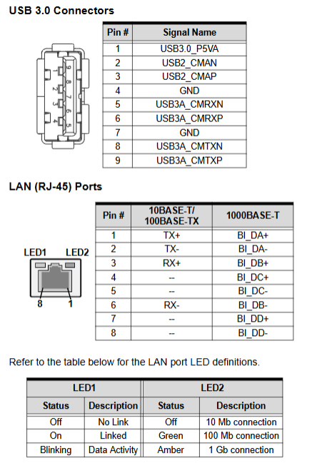
2 x RJ45 Gigabit Ethernet ports (LAN1 supports AMT9.0)
1 × DB15 VGA display
2×USB3.0
On board pin expansion IO
4 x USB 3.0 pins, 4 x USB 2.0 backplane interface
4 x SATA III 6Gbps (supports RAID0/1/5/10, AHCI)
6 serial ports COM1~6: COM1 can switch RS232/422/485, and the remaining 5 RS232 ports
DVI-D output pin (optional baffle cable)
PS/2 keyboard and mouse pin, HD Audio daughter card interface (DB-Audio2)
System panel pins (power button, restart, hard drive LED, buzzer)
4-pin temperature control interface for CPU fan and system fan
4. Bus expansion capability
Main PCIe Gen3 x16 slot: configurable as 1 × x16/2 × x8/1 × x8+2 × x4
Secondary Expansion: PCIe x4 (detachable 4×1)+32bit/33MHz Traditional PCI (TI XIO2001 Bridge)
5. Network Controller
LAN1:Intel I217LM PHY, Supports AMT9.0, PXE, WOL
LAN2: Intel I211-AT Gigabit Controller
6. Management and Security Hardware
TPM 1.2 (Infineon SLB9635 TT): Key Encryption, VPN, 802.1X Authentication, File Encryption;
WDT watchdog: 1~255 seconds/1~255 minutes programmable, automatic system reset upon timeout;
Hardware monitoring: real-time collection of CPU/motherboard temperature, fan speed, and various DC voltages;
Intel AMT9.0: Out of band remote management, remote power on/off, troubleshooting;
Intel VT virtualization, TXT trusted execution environment.
7. Mechanical and environmental indicators
Size: 338mm (length) × 126mm (width) Standard total length PICMG1.3
Working temperature: 0 ℃~60 ℃; Storage temperature: -20 ℃~80 ℃
Humidity: 10%~90% RH, no condensation
Certification: CE, FCC Class A Electromagnetic Compatibility
Power supply: ATX 12V onboard power interface, requiring industrial chassis power supply
8. Support for operating systems
Windows 7 SP1 64bit、Win8.1 64bit、Windows Server 2008 R2; Fedora19, RHEL6.5, Ubuntu 13.10 64 bit Linux.
9. Power consumption test (tested on 4 types of CPUs)
The manual tests the overall power consumption of four CPUs, namely 84W Xeon, 45W low-power Xeon, i3, and Celeron, under S1 standby, S4 sleep, S5 shutdown, system idle, normal load, and full load conditions. It also distinguishes between BIOS energy-saving (EIST/C-state) on/off states, providing reference for chassis cooling and power source selection.
Hardware Installation Chapter
1. Standard packaging list
SATA data cable, USB 3.0 ribbon cable, COM1/2 ribbon cable, COM3-6 expansion cable, driver CD, this user manual; Operation requires anti-static wristbands/anti-static bags.
2. CPU installation steps (LGA1150)
Disconnect the power supply from the motherboard, press down on the lock rod to unlock the carrier board;
Remove the socket protection cover and align the CPU triangle with the Pin1 positioning point of the slot;
Place the CPU gently vertically and strictly prohibit violent pressing;
Close the carrier board and fasten the locking rod for fixation.
3. Installation of radiator
Apply thermal grease evenly on the surface of the CPU, install a matching cooling fan, and connect the fan 4-pin plug to the motherboard FAN1 (CPU fan). If there is no heat dissipation, the CPU and motherboard will be burned.
4. Memory installation
Open the DIMM slot buckle, align the memory gap, and press down vertically until the buckle automatically locks; Dual channel requires two memory channels with identical capacity/specifications.
5. Jumpers and DIP switches
JBAT1 (Clear CMOS): 1-2 is normal, 2-3 is short circuited to clear BIOS;
JBAT2 (Clear RTC): Clear system time and CMOS; To restore default settings, two jumper wires need to be short circuited simultaneously;
SW13 DIP switch: controls COM1 serial port mode
1ON/2OFF:RS232
1ON/2ON:RS422
1OFF/2ON:RS485
6. Driver installation process (Windows 7 64 bit)
The driver CD contains a complete set of drivers, which are installed in order: chipset → graphics card → network card → ME management engine → USB 3.0;
If RAID/AHCI is required, the system installation phase preloads the Intel RST fast storage driver through F6.
Appendix A: Complete AMI UEFI BIOS Setup Guide
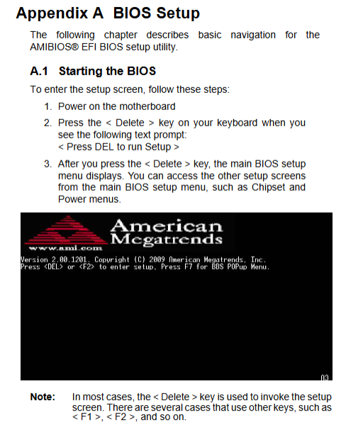
Press DEL to enter BIOS, which is divided into six menus: Main, Advanced, Chipset, Boot, Security, and Exit. Key configuration items:
Main: System time, BIOS version, memory information, administrator privileges;
Advanced Settings
ACPI: sleep S1/S3, power outage recovery strategy;
Trusted Computing: TPM switch;
CPU configuration: VT virtualization, number of cores, XD protection;
SATA: AHCI/RAID/IDE mode, hot swappable, interleaved boot;
Intel TXT: Trusted Execution Environment (TPM+VT enabled);
IGD graphics card: shared video memory (128/256MB), multi screen output;
USB: Legacy USB compatible, XHCI/EHCI switching;
Super IO: 6-way serial port switch, serial port redirection;
H/W Monitor: Intelligent fan speed regulation, temperature threshold;
AMT configuration: remote management, BIOS/OS watchdog switch;
Console redirection: Serial port remote console (supporting ANSI/VT100 terminals);
Chipset chipset
VT-d IO virtualization, priority graphics card (IGBT/PEG discrete graphics), PCIe port switch, ME management engine subsystem;
Boot startup: device priority, boot NumLock, quiet LOGO, CSM compatibility module;
Security: administrator/user two-level startup password;
Exit: Save/discard modifications, restore factory default, temporarily start device overwrite.
Appendix B: Watchdog WDT
Function: Automatic hardware reset for system freeze timeout, supporting dual timing units of seconds/minutes;
Supporting: The driver CD provides C language example code to operate the ITE IT8783 Super IO chip register configuration WDT duration and reset pin.
Appendix C: System Bottom Hardware Resources
Complete listing of the underlying hardware resources of the motherboard for industrial control driver development and device conflict resolution:
System memory address mapping (BIOS, APIC, VRAM, SMM area);
DMA channel allocation;
I/O port address table (SIO, serial port SATA、PCI、 Parallel port);
IRQ interrupt allocation (two sets of PIC traditional mode and APIC advanced mode);
PCI device bus/device/function number mapping;
PCI interrupt routing table.