ADLINK ACL-7225 ISA 16 channel relay output+16 channel isolated digital input card
Product positioning and core functions
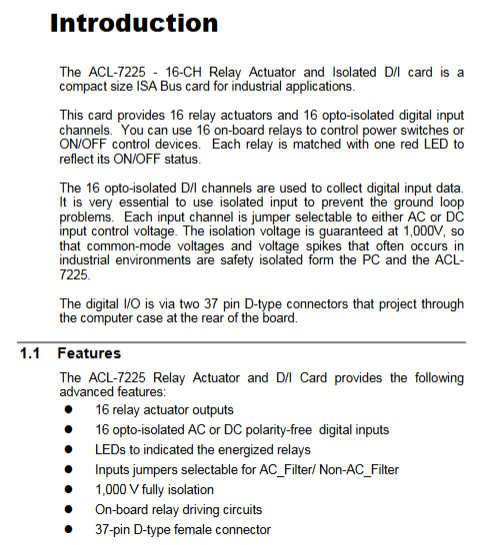
ACL-7225 is a compact ISA bus industrial switch card that integrates 16 relay outputs and 16 non-polar optocoupler isolated digital inputs. It is specifically designed for industrial equipment start stop, limit acquisition, and high-power peripheral driving, relying on 1000V channel isolation to eliminate on-site ground loop interference.
Core hardware features
16 relay outputs, each with a red status indicator light; Distinguish between Form A single blade and Form C double blade contacts;
16 PC814 optocoupler isolation DI, single channel jumper with optional AC/DC signal input, polarity free compatibility;
Channel to channel/channel to ground isolation withstand voltage of 1000V, resistant to industrial high-voltage pulses;
Dual IO interface: rear 37 pin D-Sub, onboard 40 pin pin, compatible with adapter cables for mutual conversion;
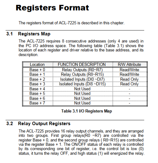
ISA bus, occupying 8 consecutive I/O addresses, using only 4 registers;
Typical application scenarios
Industrial equipment start stop control, energy management, high-power contactor drive, laboratory automation, limit switch monitoring, equipment contact status acquisition.
Complete electrical specifications
1. Relay output (16 channels)
Contact type:
R0~R4, R8~R12: DPDT dual blade Form C (common terminal COM, normally open NO, normally closed NC)
R5~R7, R13~R14: SPST single blade Form A (COM+normally open NO only)
Contact capacity: 120VAC/0.5A or 24VDC/1A, bifurcated contact structure, maximum contact resistance 100M Ω;
Action characteristics: typical 5ms suction/release; coil power supply+12V/33mA;
Board power consumption: Whole machine+5V typical 310mA, when all relays are closed+12V maximum 550mA.
2. Isolate digital inputs (16 channels)
Optocoupler device PC8141000V isolation; Input without polarity;
Signal compatibility: DC 5~24V, AC 50~1000Hz AC signal;
Single channel built-in 1.2k Ω current limiting resistor;
Response speed: 20 μ s without AC filtering, 2.2ms with AC filtering enabled;
3. General mechanical environment
Bus: IBM PC-AT ISA;
Size: 177mm × 122mm;
Working temperature range: 0-50 ℃, storage: -20~80 ℃; Humidity of 5-95% without condensation;
Interface: Rear 37 pin D-Sub, onboard 40 pin pin.
Hardware installation and jumper/dip configuration (Chapter 2 Core)
1. Anti static specifications for unboxing
The board contains static sensitive optocouplers and relay driver chips, and must be operated with anti-static pads and grounding wristbands; Damaged boards are prohibited from being powered on.
List of supporting materials: ACL-7225 motherboard, 2 DB37 male cables, 40pin to 37 pin flat adapter cable, driver CD, and this manual.
2. SW1 six level DIP dialing: base address setting
I/O address range 0x200~0x3FF, factory default base address 0x300;
The dialing corresponds to ISA address lines A3~A8, with A9 fixed at high level and A0/A1/A2 hardware grounded;
Occupying 8 consecutive I/O addresses, only four registers from BASE+0 to BASE+3 are actually valid.
3. JP1~JP16 sixteen input jumpers (each channel is independently configured)
Short circuit DC mode (factory default): DC 5~24V input;
Short circuit AC mode: compatible with 50~1000Hz AC input, built-in RC filter extends response to 2.2ms.
4. Definition of dual interface pins
CON2 (rear 37 pin D-Sub): DI0~DI7, all contacts of relays R0~R7 (COM/NO/NC);
CON1 (onboard 40Pin pin pin): all contacts of DI8~DI15 and relays R8~R15;
The matching 40Pin to 37 Pin ribbon cable can unify all channels and lead them out to the rear panel, making it convenient for chassis wiring;
DI input A/B has no polarity, and the positive and negative connections can be freely swapped.
Register Mapping and Low Level Programming (Chapter 3)
1. Register address table (only 4 valid ports)
Offset address read/write attribute function
BASE+0 R/W relay R0~R7 control register (bit0=R0)
BASE+1 R/W relay R8~R15 control register (bit0=R8)
BASE+2 read-only isolation DI0~DI7 status reading
BASE+3 read-only isolation DI8~DI15 status reading
2. Relay control logic
Register corresponding bit 1: coil engagement; Bit set to 0: coil disconnected; Power on/reset all relays disconnected;
Form C (Double Knife): bit=1 COM to NO; bit=0 COM to NC;
Form A (single blade): bit=1 COM conducts NO; bit=0 completely disconnects.
Support register readback, which can obtain the current relay switch status in real time.
3. DI reading logic
When there is voltage input, the optocoupler conducts and the corresponding bit is set to 1; The no signal bit is 0; Direct IN instruction reads bytes.
4. Bottom level programming examples
Provide native IN/OUT port read and write examples for BASIC and C languages, allowing direct control of IO without the need for advanced libraries; DOS CD comes with built-in tool programs and demo source code.
Software Support Solution
Free DOS native library: The CD comes with C header files, tool programs, and sample code, allowing direct operation of ISA ports;
Windows Business Suite (requires procurement authorization)
ACLS-DLL1: Windows 95/98/NT dynamic library, supporting VB/VC/Delphi;
ACLS-LVIEW: LabVIEW specific VI driver;
Development language compatibility: assembly, BASIC, C, PASCAL for low-level port programming.
Appendix A: Relay Inductive Load Protection Circuit (Key Practical Content)
The disconnection of inductors (solenoid valves, motors, contactors) by relays will generate reverse high-voltage breakdown contacts, providing four standard protection schemes:
RC impedance capacitance absorption: universal for both AC and DC; Select 0.5~1 Ω/V resistor and 0.5~1 μ F non-polar capacitor;
Continuation diode: only DC load, reverse withstand voltage ≥ 10 times the power supply voltage;
Combination of diode and voltage regulator: Shortens release delay, suitable for DC devices that require fast shutdown;
Varistor scheme: Suitable for both high and low voltage AC/DC, suppressing peak voltage during disconnection.