ADLINK cPCI-6530 series 6U CompactPCI single board computer
Product positioning and core overview
CPCI-6530 is a fourth generation Intel Haswell architecture 6U CPCI high-performance control blade that supports three working modes: system slot host/peripheral slot slave/independent single machine. It is equipped with BMC to achieve IPMI remote machine management and is aimed at military, aviation, rail transit, and high-end industrial measurement and control; Onboard ECC seismic resistant memory, multiple network ports, multi-channel high-speed expansion (PMC/XMC), rich local storage, supporting wide temperature and strong vibration industrial environments.
Core advantages
Dual ECC memory architecture (onboard soldered+slot memory), high seismic resistance;
Dual CPU options (low-power i5/high-performance i7), passive cooling;
Dual expansion PMC/XMC, can be connected to external sports cards and acquisition cards;
Complete IPMI 2.0 with hardware sensors, remote power on/off/fault alarm;
Front and rear separated IO (front panel debugging+RTM rear expansion), up to three independent display outputs;
Hardware watchdog, TPM encryption, and AMT remote operation and maintenance triple security mechanism.
Overview of Hardware Specifications
Processor and chipset
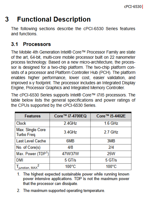
Choose between two CPUs
Model Core/Thread Frequency/Turbo Cache TDP
I5-4402E 2-core 4-thread 1.6GHz/2.7GHz 3MB 25W (low power consumption)
I7-4700EQ 4-core 8-thread 2.4GHz/3.4GHz 6MB 45W (can reduce 37W)
Supports hyper threading, Turbo 2.0, VT-x/VT-d virtualization, vPro, Intel anti-theft technology.
Chipset: Mobile QM87 Lynx Point PCH, PCIe 2.0, integrated with multiple SATA/USB/Gigabit controllers.
Graphics card: The CPU is equipped with HD4600, supporting DX11.1 and OpenGL 3.2, with up to three independent displays (front DVI+rear DVI+eDP).
Memory (dual channel ECC DDR3L-1600, total maximum 16GB)
Channel 1: Onboard soldered ECC memory, up to 8GB (earthquake resistant, preferred for automotive/military applications)
Channel 2: Slot style ECC SO-DIMM, up to 8GB
Voltage 1.35V low voltage, industrial wide temperature stability.
CompactPCI bus specification
Compatible with PICMG 2.0 (32/64bit PCI 66MHz), 2.1 hot swappable, 2.9 system management, 2.16 packet switched backplane; The board supports three operating modes:
Host mode: System slot master control, managing the entire chassis peripherals;
Universal Slave Mode: Peripheral Slot, Interworking with System Slot Host PCI;
Satellite independent mode: peripheral slot, disconnect CPCI bus, independent standalone operation (SW-POD1 dip switch).
Backplane connectors J1/J2/J3/J4/J5 respectively carry PCI signals, IPMB management, rear IO, PMC expansion, and video/peripheral signals.
Network (totaling 4 gigabit channels)
Front end 2 x Intel I210 Gigabit (one of which supports Intel AMT9.0 remote management);
Rear RTM expansion with an additional 2 I210 Gigabit channels, compliant with PICMG2.16 switching standard.
Serial port resources
CPCI-6530V front 1 RJ45 COM (RS232/422/485 dial-up switching);
RTM rear can support up to 2 RS232/422/485 channels;
IPMI dedicated debugging serial port COM6.
USB resources
CPCI-6530V front 2 x USB 3.0+1 x USB 2.0;
CPCI-6530 front 1 x USB 3.0+1 x USB 2.0;
RTM rear 6-channel USB 2.0.
Storage Interface (Multi Form Industrial Storage Adaptation)
Universal mSATA slot (both models come standard);
CPCI-6530V has a unique onboard 2.5-inch SATA SSD slot that can replace CFast adapters;
Onboard 1 SATA 7pin;
RTM rear expansion with 3-channel SATA 3Gb/s;
All support Intel Fast Storage RAID/AHCI/IDE mode.
Expansion slot PMC/XMC
CPCI-6530V: 1 slot, optional 64bit/133MHz PMC or PCIe x8 Gen2 XMC;
CPCI-6530: 2 independent PMC/XMC slots;
Equipped with PCIe to PCI bridge chip, supports 3.3V VIO level switching (dip SW_VIO1), and can enforce PCI bandwidth/clock limitations.
Security hardware
TPM1.2 (optional): Atmel AT97SC3204, hardware SHA1 encryption, 2048 bit key, voltage/frequency tamper proof, memory encryption;
Hardware watchdog WDT: Programmable timeout from 1s to 15300s, reset the entire machine after timeout, with supporting C routine;
IPMI BMC: whole machine sensor monitoring, remote power on/off, fault logs, hot plug management;
RTC button battery BR2032, saving BIOS and clock.
Environment, power consumption, certification
temperature
Standard working temperature: -20 ℃~+70 ℃;
Extreme wide temperature range: -40 ℃~+85 ℃ (i5/i7 TDP reduction+forced air cooling);
Storage: -50 ℃~+100 ℃, humidity 95% RH, no condensation.
Vibration and shock: working at 2Grms 5~500Hz; Non working 20G/11ms impact; Mechanical storage will lower the seismic resistance level, SSD is recommended.
Power consumption (i7 full load)
DOS standby: 47.08W; Win7 standby: 33.86W; CPU full load: 75.89W; whole machine copying: 58.87W.
Certification: CE, FCC Class A; Passive radiator without fan option.
Size: Standard 6U CPCI, 233mm × 160mm, 4HP single slot width.
Board interface, dialing and buttons
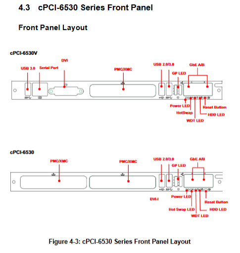
Distinguishing between two board layouts
Definition of Front Panel LED Indicator Light
LED color status description
Power LED red/green red=ready for power on; Green=POST self-test passed; Turn off=power outage
WDT alarm, orange, normally off, flashing=watchdog timeout
Hard disk LED flashing blue=storage read/write
Hot swappable blue constant light=can be unplugged; Flash flash=shutdown process; Slow flashing=abnormal voltage
Equipped with front reset button SW8.
Key DIP Switch Function
SW1-RTC reset, clear CMOS;
SW2: One click loading of BIOS default parameters;
SW7 (serial mode): Control the front COM1, ON/OFF combination switch RS232/422/485;
SW-POD1: Core mode switching (1-pin=Universal/Satellite Independent mode; 2-pin=with or without chassis management module CMM);
SW_VIO1: PMC IO level, ON=3.3V,OFF=5V;
SW-PMC1: Mandatory PCI bandwidth/clock (32-bit, 66MHz, PCI-X disabled, etc.);
SW4/SW9/SW11/SW-COMDEG1: Dedicated for debugging, factory default all OFF, prohibited from modification.
Complete definition of connector pins
The manual includes a list of all interface pins: USB2.0/3.0, RJ45 Gigabit Ethernet, DVI-I, RJ45 to DB9 serial port, SATA7Pin/with power supply CFast、PMC、XMC、 Backplane J1~J5 all CompactPCI bus pins.
Hardware installation process
Installation in four major components, anti-static throughout the process, and wearing a grounded wristband:
MSATA solid-state installation: Position the onboard slot and secure it with two screws;
2.5-inch SATA SSD (only 6530V): Install metal bracket → Secure hard drive → Dock adapter board to onboard SATA → Lock the entire machine;
PMC/XMC daughter card: Remove the front panel cover, align with the slot and press, and tighten the four screws at the bottom of the board;
Chassis insertion and removal specifications: Loosen the upper and lower handles → Push into the slot → Tighten the handles+lock the panel screws, supporting hot plugging process.
Drivers and supporting software
Supporting operating systems
Windows7/8 32/64、RHEL6.4、Fedora14、VxWorks6.9, Other systems can be customized with drivers.
Driver installation sequence (Windows)
Chipset driver → HD4600 graphics card → I210 network card → Intel RST storage → USB 3.0 → sound card → AMT management engine.
Watch dog tool WDT
Based on the IT8783 Super IO chip, it provides a complete C read/write register routine, supports software start/stop, overload countdown, alarm LED linkage, and can integrate user measurement and control programs to achieve automatic reset in case of system failure.
AMI EFI BIOS complete setup
Press Del to enter the startup menu, which is divided into 6 main menus and supports keyboard shortcuts (F2 restore last time, F3 optimize default, F4 save exit):
Main page: System time, BIOS version, administrator permissions;
Advanced Settings (Core)
ACPI sleep, TPM security switch, CPU turbo/hyper threading/virtualization;
SATA mode (IDE/AHCI/RAID), Intel AMT/anti-theft;
USB、 Hardware voltage and temperature monitoring, 6-channel serial port console redirection;
Chipset chipset: PCIe channel splitting VT-d、 Core display memory allocation (32M~1024M adjustable), memory timing;
Boot boot: boot sequence, quick boot, CSM compatibility;
Security: administrator/boot password, hard disk encryption;
Save&Exit: Save/discard configuration, factory reset, single boot overwrite.
IPMI whole machine management
IPMC onboard management controller
Following IPMI 2.0 and PICMG2.9, it communicates with the upper computer through COM6 serial port (IO0x2F09600 baud), runs independently of the main CPU, and can still monitor the chassis even when powered off.
Support core IPMI commands
Device ID reading, cold/hot reset, watchdog configuration, sensor threshold, event log SEL, FRU hardware information reading, hot plug management.
List of built-in hardware sensors
BMC watchdog, 3.3V/5V/12V voltage, CPU temperature, system temperature, can be configured with overvoltage/overheating automatic power-off/restart.
IPMB Address Mapping
The chassis slots correspond to independent bus addresses, and multiple blade chassis do not conflict with each other, supporting distributed monitoring.
Safety regulations and after-sales service
Operation taboos: It is prohibited to plug and unplug the board with electricity or disassemble it in non anti-static environments; Incorrect lithium battery model can cause explosion, only BR2032 of the same specification can be replaced;
Repair restriction: Only authorized engineers are authorized to repair, and damage caused by water ingress/falling/abnormal power supply is not covered by warranty;
Environmentally friendly scrapping: The entire machine needs to be recycled according to local electronic waste regulations and comply with RoHS without harmful substances;
Supporting accessories: RJ45 to DB9 serial cable, SSD bracket, mSATA kit, rear RTM module cPCI-R6500/R6700 (expanding rear IO and multi display).
Overall application scenario
Military/aerospace 6U CPCI reinforced measurement and control platform;
Rail transit on-board wide temperature industrial control host;
Distributed multi axis motion control (paired with AMP series motion cards);
High speed signal acquisition and automated testing equipment;
Remote unmanned machine room and base station monitoring (IPMI+AMT remote operation and maintenance).