ADLINK DIN-812M Terminal Block Installation Manual
Basic Information
Product model: DIN-812M, Linghua dedicated 2-axis motion adapter terminal board
Hard compatibility limitation: Only compatible with PCI-8132 sports control card, prohibited from pairing with any other sports card
Core positioning: Designed specifically for Mitsubishi J2S servo/stepper motors, providing two sets of mutually exclusive wiring solutions, integrating limit origin IO, universal DI/DO, comparison trigger, encoder feedback, emergency stop switching functions, and supporting DIN rail industrial installation.
Overall hardware layout and connector classification
1. Purpose of core interface
Interface specification and function description
CN2 100 pin SCSI backend bus, one-to-one connection to PCI-8132 motion control card
CN1 2-pin terminal external isolation 24VDC power input (DC24V ± 5%), providing EX+24V, EXGND
CNA1/CNB1, CNA2/CNB2 20 pin 3M connector Mitsubishi J2S servo dedicated shaft interface (one set each for shaft 1 and shaft 2)
SJ1/SJ2 10 pin needle set stepper/third-party servo pulse interface (pulse+direction)
SJ3/SJ4 10 pin external encoder feedback channel
IOIF1~IOIF7 Mechanical IO/Universal DI/DO/Trigger limit, origin, deceleration, isolated digital input/output, position comparison COMP signal
HD1/HD2 6-pin backup servo auxiliary interface servo enable, ready, alarm, external emergency stop expansion
J1/J2/J3 jumper group emergency stop logic, DI common terminal level configuration
Real time display of external input level status such as limit and origin by the LED indicator light group IOIF
2. Key wiring taboos (mandatory rule)
The internal signals of CNA/CNB (Mitsubishi servo) and SJ (stepper) on the same axis are directly short circuited, and simultaneous wiring is prohibited, otherwise the short circuit will burn out the drive/control card; Choose one of the two wiring methods.
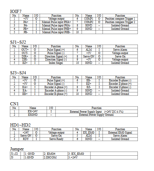
Complete pin functionality of each connector
1. CNA+CNB (Mitsubishi J2S servo specific, one set of 20 pin cables per axis)
CNA: Differential pulse OUT ±, direction DIR ±, encoder EA/EB/EZ Z-phase, servo ready RDY, in place INP, servo enable SVON, isolated ground IGND
CNB: ± limit PEL/MEL, origin ORG, acceleration/deceleration PSD/MSD, external emergency stop Ext. EMG,+24V isolated output
2. SJ1/SJ2 (stepper/universal servo pulse port)
Differential pulse OUT ±, direction DIR ±, encoder Z index EZ+, SVON enable, ALM alarm, two-way+5V output, isolated ground IGND
3. SJ3/SJ4 (external encoder channel)
A/B/Z three-phase differential encoder feedback,+5V power supply, isolated ground IGND
4. IOIF grouping function
IOIF1/2: Mechanical IO (PEL positive limit, MEL negative limit, ORG origin, PSD forward deceleration, MSD reverse deceleration, external reset RES)
IOIF3/4: Isolated Digital Output DO Group
IOIF5/6: Isolated Digital Input DI Group
IOIF7: Manual differential pulse input PA/PB, two-way position comparison output COMP1/COMP2 (TTL level, used for positioning triggering),+5V power supply
5. HD1/HD2 (servo assisted backup port)
24V output, SVON servo enable, RDY ready, ALM alarm, external emergency stop Ext.EMG, isolated ground IGND
6. CN1 power supply terminal
EX+24V (positive power supply), EXGND (isolated ground), providing isolated power supply for all external sensors and servo IO
Jumper J1/J2/J3 configuration logic
1. J1 (axis 1), J2 (axis 2): Servo emergency stop EMG switching
1-2 Short circuit: forced grounding of EMG inside the board, external Ext.EMG pin failure, unable to external emergency stop
2-3 Short circuit: External Ext. EMG connected to servo emergency stop circuit, short circuit GND to trigger motor emergency stop
2. J3: Digital input DI common terminal DI-COM level
1-2 Short circuit: DI common terminal connected to GND, compatible with NPN sensor
2-3 Short circuit: DI common terminal+24V, compatible with PNP sensor
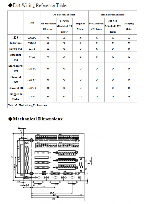
Wiring Selection Quick Check Table (O=Wiring Required, X=No Wiring Required)
Interface Mitsubishi J2S servo (without external encoder) Mitsubishi J2S servo (with external encoder) stepper motor
CNA/CNB O O X
SJ1/SJ2 X X O
SJ3/SJ4 X O X
IOIF1-7 All O All O All O All O
Mechanical specifications
Installation standard: DIN rail installation, with millimeter size engineering drawings attached
The overall length is 123mm, with connectors arranged on the entire panel and fixed installation holes reserved on both sides;
All signals are equipped with IGND isolation ground, isolated digital IO, and suppressed ground loop interference.
Description of supporting cables
Mitsubishi J2S servo needs to purchase Lingyuan factory 20 pin one-to-one dedicated cable; The sports card and terminal block use standard 100 pin SCSI cables.