ADLINK DIN-814Y Terminal Board
Product positioning and core functions
DIN-814Y is a 4-axis dedicated adapter terminal block that enables signal isolation and conversion between motion control cards and Yaskawa servo and stepper motors. It supports independent 4-axis control on a single block and provides two sets of mutually exclusive wiring interfaces for each axis
CNIF: Connect with Yaskawa servo amplifier dedicated interface;
SJ: Interface with stepper driver pulse interface;
Important restriction: CNIF and SJ cannot be wired simultaneously on the same axis. Internal signals can be directly short circuited, and mixing them can cause signal short circuits and damage to the equipment.
CN2: Connect the Linghua motion control card through a 100 pin SCSI-II cable;
CN1: External 24VDC isolated power input (± 5% tolerance), providing isolated power supply for limit, origin, and servo IO;
External interfaces of each axis: CNIF1~CNIF4 (4-axis Yaskawa servo), SJ1~SJ4 (4-axis stepper), IOIF1~IOIF4 (4-axis mechanical limit/origin IO), BH1~BH4 (Yaskawa servo expansion reserved pins);
Status indication: Each axis is equipped with BH indicator lights, which display PEL positive limit, MEL negative limit, and ORG origin signal levels respectively.
Definition and function of all connector pins
1. CNIF1~CNIF4 (Yaskawa servo 50 pin main interface, single axis complete servo signal)
Divided into three categories: output signal (control card → servo), input signal (servo → control card), and isolated ground IGND:
Pulse/Direction Differential Output: OUT+/OUT – Pulse, DIR+/DIR – Direction;
Servo enable SVON, alarm clear ERC, 3-digit fault code AL01/AL02/AL03;
Encoder feedback differential: EA+/EA – (A-phase), EB+/EB – (B-phase), EZ+/EZ – (Z-zero phase);
Absolute value encoder matching: BAT+/BAT – encoder battery, PSO+/PSO – encoder S phase;
Servo simulation commands: V-REF speed command, T-REF torque command;
Servo status feedback: RDY servo ready, INP in place, ALM servo alarm;
Current limiting input:/P-CL forward current limiting,/N-CL reverse current limiting, P-CON proportional control;
External output+24V, SEN absolute encoder reset, PL1 collector 12V output;
All analog and digital signals share an isolated ground IGND, which is electrically isolated and anti-interference.
2. IOIF1~IOIF4 (4-axis mechanical limit/origin IO interface)
Universal limit input for each axis, signal is 24V isolated input:
PEL: Positive hard limit;
MEL: Reverse hard limit;
ORG: Origin Regression Sensor;
PSD: Forward deceleration signal;
MSD: Reverse deceleration signal;
RES: External reset;
+24V isolated power supply, IGND isolated ground;
PSD pin function differentiation (key differentiation)
PCI-8134: PSD is only used as a forward deceleration input;
PCI-8164/PXI-8164/MPC-8164: PS1/PS2 corresponds to axis 0/1 comparator CMP, PS3/PS4 corresponds to axis 3/4 latch LTC.
3. SJ1~SJ4 (10 pin pulse interface for stepper driver)
Simplify pulse differential signal and adapt to stepper drive:
Pulse differential OUT+/OUT -, directional differential DIR+/DIR -;
EZ+encoder Z-phase index input;
SVON step enable, ALM driver alarm;
Two channels+5V output, isolated ground IGND.
4. BH1~BH4 (Yaskawa servo expansion backup interface)
Reuse all CNIF extended analog/encoder pins to expand the special functions of Yaskawa servo. The pins include SEN, BAT, PSO, V-REF, T-REF, current limiting, fault coding, PL1,+24V, etc. Refer to the Yaskawa servo manual for wiring.
5. CN1 (external power supply 2-pin terminal)
EX+24V: Positive pole of external 24VDC power supply;
EXGND: external power isolation ground;
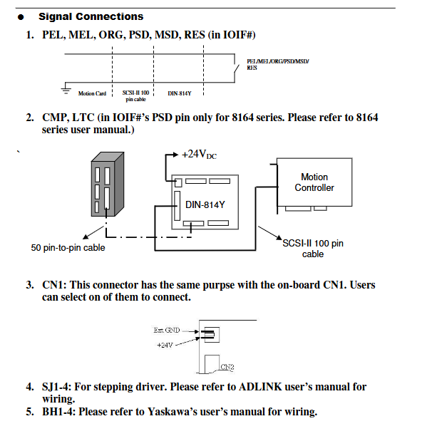
The onboard CN1 and the external CN1 have completely identical functions, and you can choose one to connect them.
Key rules for signal and wiring
Isolation design: All external sensors and servo signals are isolated by IGND ground, separated from the digital ground of the motion card, to suppress ground loop interference;
Axis interface mutual exclusion: Only one of CNIF (servo) and SJ (stepper) can be connected to the same axis. If the internal circuit is short circuited, the two wires will be short circuited;
Power supply specification: External input DC24V ± 5%, providing isolated driving power supply for limit, origin, and servo IO;
Cable matching: The terminal block and sports card use 100 pin SCSI-II cable; The terminal block adopts 50 pin one-to-one cable for external servo/stepping;
Indicator light logic: The BH side three color LED corresponds in real-time to the PEL/MEL/ORG input levels, quickly troubleshooting limit and origin sensor faults.
Mechanical dimension specifications
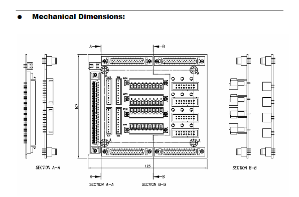
The overall length is 123mm and the height is 107mm; the standard DIN rail installation version has reserved fixing holes on both sides;
The three views include A-A and B-B sections, which clearly display the height and depth of the front and rear connectors, and are compatible with the standard guide rail installation of industrial control cabinets.
Precautions
Device compatibility red line: Only compatible with PCI-8134/8164, PXI-8164, MPC-8164 four Linghua sports cards, only compatible with Yaskawa pulse servo/stepper drive. Mixing other brands of servos and sports cards may result in signal mismatch and hardware burnout;
Wiring taboos: Single axis servo/stepper interfaces cannot be wired simultaneously;
The PSD function varies with the model of the sports card, and programming and wiring need to correspond to the card manual;
The BH expansion port is only used for special function expansion of Yaskawa servo, and conventional servo control only requires the use of CNIF;
Before installation, confirm that the 24V power supply voltage is within the ± 5% range to avoid damage to sensors and servo IO;
The limit and origin signals are isolated inputs, and it is recommended to use an NPN/PNP open collector sensor with an onboard 24V isolated power supply.