ADLINK MXC-3300/MXC-3340 Fanless Scalable Embedded Industrial Computer
Product Introduction
Product Positioning
MXC-3300/MXC-3340 are fanless embedded industrial computers based on the Intel Alder Lake-N platform, with low power consumption and strong multimedia acceleration capabilities; Rich isolation industrial I/O capabilities; MXC-3340 provides PCIe expansion slots. Targeting harsh industrial scenarios such as industrial automation, building management, and intelligent transportation.
Core Features
CPU:Intel N97, 4-core, maximum 3.6GHz, 12W power consumption
Memory: Single slot DDR5 SO-DIMM 4800MHz, maximum 16GB
Display output: 1 x HDMI 2.0+2 x DP 1.4, maximum 4K@60Hz Multiple independent displays
Network: 4-way Intel i210IT Gigabit Ethernet, supporting PCIe, IEEE1588 time synchronization, jumbo frames WOL
Industrial isolation interface: 2.5kV isolated CAN bus; 2-way isolation RS-232/422/485; 1.5kV isolation 8DI+8DO digital quantity IO
Storage: 2.5-inch SATA SSD; M. 2 M-Key (NVMe), M.2 E-Key (WIFI6/BT), M.2 B-Key (4G+SIM card)
Safety: Onboard TPM2.0
Power supply: 9-36V wide voltage DC input
Expansion: MXC-3340 has 3 exclusive PCIe slots (1 x PCIe x8, 2 x PCIe x4); MXC-3300 without PCIe slot
Environment: Operating temperature -20 ℃~60 ℃ (DC power supply; upper limit of 50 ℃ when using an external adapter); Storage -40~85 ℃; 95% non condensing humidity at 40 ℃; Through IEC vibration impact ESD、 Surge EMC testing; Certified CE/FCC Class B UL62368、CB。
Operating system support: Windows 10 IoT LTSC2021, Ubuntu 22.04
Size
MXC‑3300:80(W) ×219(D) ×210(H) mm
MXC‑3340:142(W) ×219(D) ×210(H) mm
Packing List
Host, 2 sets of wall brackets, power wiring terminals; SSD、 Memory and M.2 module are not standard equipment.
Specification Summary Table
Project MXC-3300 MXC-3340
PCIe expansion without 1 x PCIe x8, 2 x PCIe x4
SSD compartment with removable SSD tray and built-in SSD compartment
I/O completely consistent 4GbE, 2COM, 2CAN, 8DI/8DO, HDMI+2DP, 4USB, audio, three-way M.2 as above
Power supply 9-36VDC 9-36VDC/24VDC
Anti vibration: 3Grms; 30G shock resistance; complete EMC static electricity, electrical fast pulse, surge, RF immunity indicators.
Functional Block Diagram
Fully display the hardware signal links of Alder Lake-N SoC with DDR5, SATA, three-way M.2, 4-port, CAN controller, serial transceiver, isolated DIO, audio, TPM, PCIe switching chips; Distinguish between motherboard and MXC-3340 dedicated backplane.
Mechanical Layout
Front panel interface description
Identification interface
A power button
B 2 × DB9 isolated COM+2 × DB9 isolated CAN
C USB3.2 Gen2
D USB2.0×2
E DB37 digital DI/DO interface
F 9-36V DC input terminal
G Audio (MIC in/Line in/Line out)
H 4-channel RJ45 Gigabit LAN
I HDMI
J Dual DP Display Output
K-status LED (WDT watchdog, HDD hard drive, diagnostic DG)
L external reset button
LED status:
PWR: Always on when turned on; S3/S4 sleep flashing; Shut down and turn off
WDT yellow: Watchdog running flashing, timeout constant on
HDD Orange: Disk Read/Write Flashing
DG green: No storage device constantly on
Engineering drawings: Provide front/rear/top/bottom/side views of two models, including installation openings and overall dimensions of the machine.
Quick Installation
All disassembly and assembly operations must be powered off.
SSD installation
MXC-3300: Loosen the screws and remove the removable tray to install the 2.5 “SATA SSD.
MXC-3340: Remove the housing cover and install the SSD bracket.
PCIe card installation (MXC-3340 only): Remove the front panel cover, remove the blocking plate, and insert the PCIe card lock.
M. Installation of Module 2
MXC-3300: Remove the 8 screws from the back cover of the entire machine and open the cover. Install M-Key/NVMe, E-Key/Wi Fi, and B-Key/4G modules separately.
MXC-3340: Remove the front cover to access the M.2 slot on the motherboard.
Wall bracket installation: Remove the screws from the back cover and lock the wall bracket.
Definition of Connectors and Pins
Front panel interface
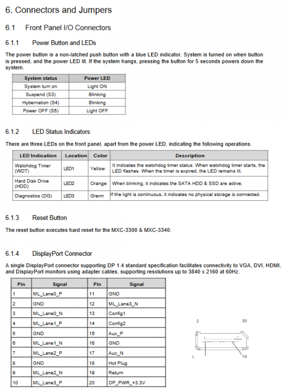
Power button: non self-locking button; Press and hold for 5 seconds to force shutdown; The reset button performs a hardware hard restart.
DP video port: DP1.4 complete pin definition.
4-channel gigabit network port i210IT: yellow light Link Act; Green/orange represents speed; Supports PCIe, IEEE1588, and WOL.
USB: 3 x USB 2.0 (0.5A per port), 1 x USB 3.2 (1A), all with overcurrent protection.
DB9-COM serial port: Switch RS232/422/485 mode in BIOS and provide a complete 9-pin signal definition.
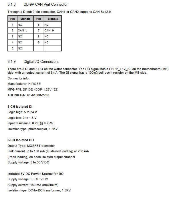
DB9‑CAN:CAN2.0B, Pin definition: CAN_S/CAN_L.
DB37 isolated DI/DO (8 in and 8 out)
DI: Optocoupler isolation 1.5kV; Input level 5-24V;
DO: MOSFET output; Continuous 100mA per channel, peak 250mA; isolated 1.5kV; requires external VDD driven relay/inductive load, requires freewheeling diode;
Complete DB37 pin allocation, accompanied by DI and DO internal circuit diagrams.
Audio interface Realtek ALC888S: Line in blue; Line out green; MIC in pink.
DC power terminal: Pin V+, chassis ground GND, V —, 9-36V wide voltage input.
Onboard internal interface
Motherboard: DDR5 memory slot; M. 2 M-Key/E-Key/B-Key slots;
MXC-3340 backplane: PCIe x8, PCIe x4 × 2.
BIOS Complete Setup (AMI Aptio Setup)
Press DEL to enter BIOS during startup; F7 brings up the one-time startup menu.
Warning: Incorrect configuration of Advanced/Chipset can cause non boot and hardware abnormalities.
Menu grouping:
Main: System version, date and time.
Advanced
CPU configuration: Core quantity switch, SpeedStep, Turbo, VT-X virtualization, VT-d, C-State power management.
Power management: ACPISleep S3/S5; Power off and restore power on (G3 status options: S0/S5/Last State); Sleep switch.
Hardware monitoring, BIOS watchdog (supports second/minute mode).
Onboard equipment: COM1/COM2 serial port mode selection RS232/422/485; Serial port terminal redirection (Console redirection, used for serial port debugging console, baud rate, flow control parameters).
TPM 2.0 security configuration: Enable/clear TPM, PCR bank settings.
NVMe device information and self check; Network Stack UEFI PCIe IPv4/IPv6.
Chipset chipset
Memory parameters, SATA controller switch; USB port separately enabled/disabled; BIOS lock.
Security: administrator password, user startup password.
Boot startup: NumLock, Quiet Boot, Fast Boot; Adjust the priority of starting devices; Priority of hard disk BBS.
Save&Exit: Save/Discard Changes; Load factory optimized defaults; EFI Shell startup.
Appendix A: Power Consumption Reference
Test conditions: 24V power supply, external peripherals, no M.2/PCIe expansion card inserted, providing idle, typical load, maximum load, S3/S4/S5 sleep power consumption; Distinguish between MXC-3300 and MXC-3340.
Only used for power selection estimation; The actual power consumption varies with the external module.
Appendix C Watchdog WDT Development Library
Watchdog function: Automatic hardware reset system when software freezes and timeout occurs.
Windows API: C/C++interfaces InitWDT(), SetWDT(), StartWDT(), ResetWDT(), StopWDT(); The time unit supports seconds/minutes.
DOS/Linux: Direct access to LPC ITE8783 IO register; Comes with complete C sample source code.
Appendix D DI/O Digital IO Windows Development Library
Windows C/C++API: GPIOInitialize; GPIORead() reads the input status; The library files can be downloaded from the official website.
Safety instructions
When disassembling and assembling the chassis, the DC power supply must be cut off, and all cover plates must be restored before powering on.
Operating temperature: DC power supply up to 60 ℃, adapter mode up to 50 ℃; Stay away from liquids and dust; Do not block the heat dissipation fins.
Built in lithium battery, there is a risk of explosion if the wrong model is replaced, and the waste battery is recycled in compliance.
The equipment is limited to controlled industrial computer rooms and can only be maintained by authorized technical personnel; Water ingress, falling, and power damage must be returned to the factory for repair.
The recommended copper wire specification for terminal wiring is 30-10AWG, with a specified tightening torque.
Warning of high temperature burns on the shell, touch again after cooling down; Use UL/IEC certified power supply.