ADLINK PXIe-3987 PXI Express Embedded Controller
Product Overview and Main Features
PXIe-3987 is a PXIe embedded controller based on the seventh generation Intel Core i7-7820EQ (3.0GHz, single core turbo frequency 3.7GHz), used for the PXI Express testing platform and meeting the PXI-5 hardware specification Rev1.0.
1. Processor and chipset: CPU i7-7820EQ; Chipset Mobile Intel QM175; DMI3.0, Bidirectional bandwidth of 8GT/s.
2. Memory: Dual channel DDR4 SODIMM, up to 32GB, supports 2133/2400MHz, non ECC no buffer memory; A 64 bit system is required to use 4GB or more of memory.
3. PXIe link capability: PCIe 3.0 switch, two modes: 4-link (× 4 × 4 × 4 × 4), 2-link (× 16 × 8); The maximum throughput of the whole machine is 16GB/s.
4. Storage: Onboard 2.5-inch SATA interface, factory pre installed 240GB SSD or 500GB HDD, SATA speed of 6Gbps, supports AHCI.
5. Rich onboard I/O interfaces
-2-channel DisplayPort video output, maximum support 4K@60Hz ;
-Dual Gigabit Ethernet (I219-LM, I210), supporting Wake on LAN;
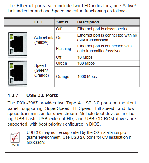
-2 USB 3.0, 4 USB 2.0;
-Micro-D 25 pin GPIB (IEEE488) controller, compatible with NI 488.2 driver;
-D-Sub9 serial port COM, BIOS optional RS-232/422/485;
-SMB trigger interface enables mutual routing between external signals and PXI backplane trigger bus.
6. Supporting operating systems: Official support for Windows 10 64 bit, other systems need to contact Linghua technical support.
7. Physical and environmental parameters
-Specification: 3U/4-slot PXI module, weight 1.0kg;
-Working temperature: SSD version 0~55 ℃, HDD version 0~50 ℃; Storage -20~70 ℃;
-Vibration and shock: meet the specifications of industrial testing equipment;
-Electrical: Provide typical, high load 3.3V/5V/12V power consumption parameters;
-Having electromagnetic compatibility A/B certification and meeting relevant EU directives.
Front panel interface, indicator lights, and onboard hardware
2.1 Front panel interface
|Component | Function|
|Reset button | Trigger with fine tools to hardware reset the entire machine|
|DisplayPort × 2 | Dual display output, requires adapter to adapt to VGA/DVI/HDMI|
|USB 3.0 × 2, USB 2.0 × 4 | Peripheral and instrument control, supporting USB boot; It is recommended to prioritize using USB 2.0 for system installation|
|Dual Gigabit Ethernet RJ45 | Each Ethernet port is equipped with link/activity lights and speed indicator lights, distinguishing between 10M/100M/1000M|
|COM port D-Sub9 | Serial port, BIOS switches to RS-232/422/485 mode, pin definitions provided in the manual|
|Micro-D GPIB 25P | External desktop instrument, requires ACL-EIEEE488-MD1-A cable, can control up to 14 instruments, up to 1.5MB/s, built-in 2KB FIFO|
|SMB TRIG interface | PXI trigger, TTL level edge trigger, programmable implementation of external signal, software trigger, routing between backplane 8-channel PXI trigger bus|
2.2 LED status indicator light
1. PW green: The power supply is normally on;
2. HD yellow: Disk activity light, flashing when reading and writing SSD/HDD;
3. USR Blue: User programmable custom indicator light.
2.3 On board hardware
1. Clear CMOS switch SW1: used to restore BIOS default configuration;
2. SATA hard drive interface: connect 2.5-inch storage;
3. CR2032 button battery: RTC real-time clock backup.
3. Getting Started chapter
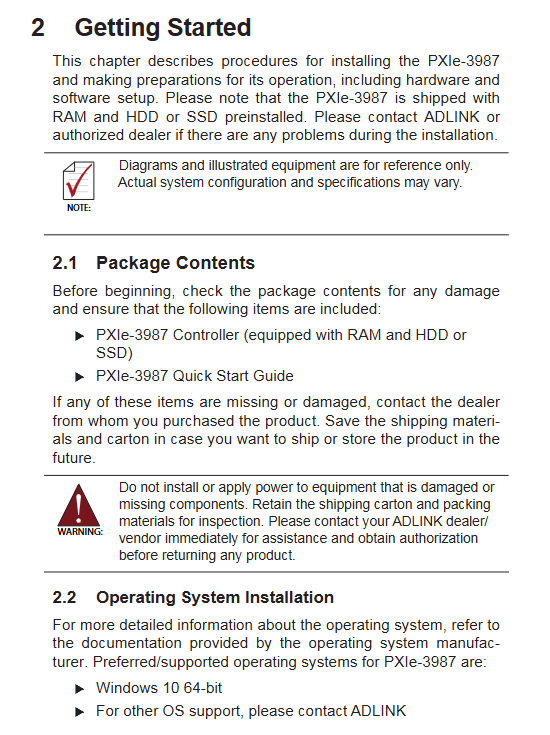
1. Packing list: Controller body (pre installed memory, storage)+Quick Start Guide; Check for damage upon receipt.
2. Steps for installing the controller
1. Electrostatic protection: anti-static wristbands, anti-static pads;
2. Remove the panel screws and release the red lock buckle;
3. Insert the PXI chassis into Slot 1 (system controller slot) and fully push it into the backplane;
4. Lock the locking buckle, tighten the panel fixing screws, and connect the external devices.
3. Hardware replacement process
-Replace SSD/HDD: Remove 5 screws from the hard drive bracket, remove the bracket, remove 4 fixing screws from the hard drive, replace and restore in reverse;
-Replace RTC battery: Power off the chassis, remove the module, pry off the old CR2032, and install the new battery with the positive pole facing upwards;
-Clear CMOS operation: Turn off the power and remove the module. Move the SW1 switch to the Clear position and wait for 5 seconds before switching back to Normal; Reinstall the computer case, press Del/ESC to enter BIOS when booting up, F9 loads the default, modifies the system time, F10 saves and exits.
4. Operating system installation
-Supports USB optical drive, USB flash drive, and USB external hard drive as boot media;
-BIOS adjusts the startup sequence; USB 3.0 is not recognized in some installation environments, and it is recommended to use the USB 2.0 interface for system installation.
Driver installation
Windows 10 has some built-in drivers, and the remaining drivers can be downloaded from the Linghua product page and need to be installed
1. Intel chipset, graphics card, network card, RST, ME driver;
2. GPIB driver;
3. PXI Trigger I/O triggers IO driver;
4. PXI platform services.
Appendix A: PXI Trigger I/O Library API
Provide C/C++, VB, Delphi development interfaces for programming and controlling SMB interfaces and PXI backplane trigger bus signal routing. Core functions:
1. TRIG_Init(): Initialize the triggering module, which must be executed before calling other functions;
2. ‘TRIG_Close()’: Close the module to release resources;
3. TRIG_SETSoftTrg(): The software generates a TTL trigger signal;
4. TRIG_Trigger_Soute(): Configure the trigger signal routing source, target, and intermediate path;
5. TRIG_Trigger_Clear(): Clear routing configuration;
6. ‘TRIG_GetSoftTrg()’: Read the software trigger level status;
7. TRIG_Trigger_Soute_Query(): Query the current routing configuration;
8. ‘TRIG_dDriverRevision()’: Read the driver version number.
The data types, return error codes, and enumeration values of various parameters in the document definition library.
Appendix B: BIOS Settings
1. Enter BIOS: Press the ‘Delete’ button to power on/restart;
2. Five main menus: Main, Advanced, Boot, Security, Save&Exit;
-Main: BIOS version CPU、 Memory and PCH chip information, system temperature and voltage statistics, operation statistics (power on times, startup times), setting system date and time;
-Advanced Menu: CPU Configuration (Hyper Threading, VT Virtualization, Turbo Boost, etc.) C‑States); Memory and graphics card configuration; Onboard devices (serial port mode switching, network port switch, SATA settings); USB configuration; Network PXE; PCIe configuration; Power management; PXIe link rate configuration; Hardware health status monitoring;
-Boot startup menu: Startup options, CSM compatibility support module, supporting two startup modes: UEFI/Legacy;
-Security menu: administrator password, user password Secure Boot;
-Save&Exit: Save/discard modifications, load default settings, temporarily overwrite startup items.
3. Shortcut keys: F9 load optimization default values, F10 save exit, F8 fail safe configuration.
Appendix C: Dual BIOS Dual BIOS
Equipped with redundant functions of main BIOS and backup BIOS: When the main BIOS is damaged (upgrade failure, etc.), hardware monitoring will automatically switch to backup BIOS startup; A backup BIOS startup prompt appears, please contact technical support to repair the main BIOS.
Appendix D: Traditional Legacy Startup Mode Settings
Factory default UEFI boot; To start Legacy BIOS, you need to modify the Boot menu, enable CSM support, and set all network/storage/video/other PCI devices to Legacy; Restore UEFI by directly loading optimized default values on F9, saving and restarting on F10.