ADLINK PXIe-3987/3977/3937 PXI Express Zero Slot Embedded Controller
Differences and commonalities in product hardware specifications
CPU Selection
|Model | Processor | Parameters|
| PXIe‑3987 | i7‑7820EQ | 3.0GHz, Ruipin 3.7GHz, 4-core|
| PXIe‑3977 | i5‑7440EQ | 2.9GHz, Ruifeng 3.6GHz, 4-core|
| PXIe‑3937 | i3‑7100E | 2.9GHz, 2 cores|
-Chipset: QM175/HM175; Dual channel DDR4-2133/2400 SODIMM, * * maximum 32GB * *, only Linghua original memory guarantees stability; A 32-bit operating system cannot use more than 4GB of memory and requires a 64 bit system.
-PXIe exchange: PCIe 3.0, maximum throughput of 16GB/s; Supports two link modes: 4-channel x4 or 2-channel x16+x8.
-Storage: 2.5-inch SATA3.0, standard 240GB SSD/500GB HDD, supports AHCI.
-Onboard I/O (three identical)
1. 2 x DisplayPort, maximum 4K@60Hz ;
2. Dual Gigabit Ethernet ports I219-LM and I210, supporting WOL network wake-up;
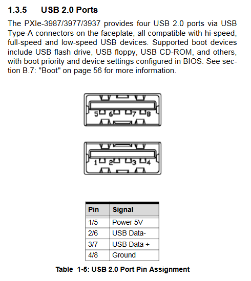
3. 2×USB3.0,4×USB2.0; It is recommended to use USB 2.0 instead of USB 3.0 for abnormal recognition during OS installation;
4. Micro‑D25 GPIB(IEEE488), Compatible with NI 488.2 API, can connect up to 14 instruments;
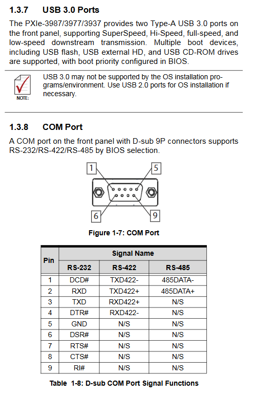
5. D-Sub9 serial port COM, BIOS switch RS-232/422/485;
6. SMB trigger interface: TTL level, realizing mutual routing between external signals and PXI backplane 8-way trigger bus TRIG0-TRIG7, software programmable.
Physics, environment, power consumption
-3U/4-slot PXI module, weighing 1.0kg;
-Working temperature: SSD version 0~55 ℃, HDD version 0~50 ℃; Storage -20~70 ℃; Humidity 5-95% without condensation; Meet the industrial indicators for impact vibration (* * Linghua original disk must be used for the indicators to be effective * *);
-Power consumption: System idle:+3.3V 5A,+5V 2.5A,+12V 2A; CPU high load:+12V can reach 8A;
-Certification: FCC, EN series A/B electromagnetic compatibility.
Front panel indicator light
1. PW green: System power supply is normal;
2. HD yellow: Disk read/write flashing;
3. USR Blue: User programmable LED;
Reset small hole: Press the needle to perform hardware hard reset.
Onboard internal hardware
1. Clear CMOS switch SW1;
2. SATA hard drive interface;
3. CR2032 RTC backup button battery.
Hardware installation and maintenance
The equipment is sensitive to static electricity, so wear anti-static wristbands and pads throughout the disassembly and assembly process.
1. Chassis installation: The PXI chassis slot 1 must be inserted into the zero slot; Align the guide rail and push it in, tighten the locking buckle, and tighten the four screws on the panel.
2. Hard drive replacement: Remove the 5 screws from the hard drive bracket, take out the bracket, remove the four corner fixing screws of the hard drive, replace the 2.5 “SATA drive, and reverse restore.
3. RTC battery replacement: Power off and remove the module, pry open the buckle, and insert * * CR2032 with the positive pole facing up * *.
4. Clear CMOS (crash/BIOS exception)
1) Turn off the power and remove the module; Set SW1 to Clear and hold for 5 seconds, then switch back to Normal;
2) Reinstall the computer case, press’ Del/Sc ‘to enter BIOS when booting up, load optimized default values on F9, modify system time, and save and exit on F10.
5. Supported operating systems: * * Windows 10 64 bit * *; Contact Linghua technical support for other systems.
6. OS installation: Use a USB flash drive/USB drive as the boot medium, and adjust the boot sequence with BIOS.
Driver software installation
Windows 10 comes with some basic drivers; The complete driver can be downloaded from the three product pages on Linghua’s official website (with universal driver files), and installation is required:
Chipset, graphics card, Ethernet, Intel ME, RST, GPIB, * * PXI Trigger I/O driver * *; Optional tools: PXI platform services, MAPS software suite.
Appendix A PXI Trigger I/O API Library
C/C++, VB, Delphi are available, and the header file ‘pxitrigo. h’ is used to configure signal routing between SMB connectors and PXI backplane trigger buses.
-TRIG_Init: Initialization (* * must be called first * *)
-TRIG_Close: Release resources, program exits call
-TRIG_SETSoftTrg: Software generates TTL trigger level
-TRIG_Trigger_Soute: Configure trigger signal source, destination, and intermediate path
-TRIG_Trigger_Clean: Clear all routing configurations
-TRIG_GetSoftTrg: Read software trigger level
-TRIG_Trigger_Soute_Query: Query the current routing configuration
-TRIG_dDriverRevision: Read driver version number
Signal source/destination options: external SMB connector, software trigger source, TRIG0-TRIG7, a total of 8 PXI backplane trigger buses.
Appendix B BIOS Settings
1. Enter BIOS: Press’ Del ‘or’ Esc ‘when booting up; Hot keys: F1 Help, F8 Restore Last Configuration, F9 Load Factory Optimized Default, F10 Save Exit.
2. BIOS five major menus
-Main: Read only hardware information (BIOS version CPU、 Memory, temperature, power consumption, power on mode, operation statistics, serial number, MAC address, etc., set system date and time.
-Advanced (Added TPM2.0 configuration item, V1.1 version update): CPU Hyper Threading/Virtualization/Turbo; Memory and graphics card; USB; TPM2.0 safety module; Serial port mode, network port switch; PCIe link parameters; Power management; PXIe link rate; Hardware health monitoring.
-Security: Administrator/user password, Secure Boot secure boot.
-Boot: Startup option; CSM compatible module; **UEFI is the factory default * *; You can switch to Legacy traditional startup mode.
-Save&Exit: Save/discard modifications, restore default, select temporary startup option.
3. Legacy Traditional BIOS Startup Settings: Select LEGACY from the Boot menu, enable CSM support, and set Network, Storage, Video, and other PCI devices to Legacy respectively; Restore UEFI directly by F9 loading default.
Appendix C Dual BIOS Backup
The motherboard has a primary BIOS and a backup BIOS. The main BIOS is damaged (upgrade failure, etc.), and the hardware automatically switches to backup BIOS startup; Startup prompt to backup BIOS activation; To restore the main BIOS, it is necessary to contact Linghua technical support.