ADLINK MXE-5500 series fanless embedded industrial computer
Chapter 1 Product Overview (Hardware Specifications, Interfaces, Structure)
Core hardware platform
Processor and chipset
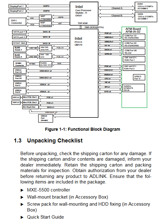
Intel 6th generation Skylake-H i7/i5/i3 industrial processor, QM170 PCH chip, dual channel DDR4 2133 memory, dual SO-DIMM slots, maximum expansion up to 32GB.
Display subsystem
Onboard Intel core display, supporting three independent display outputs: 2 x DisplayPort 1.2+1 x DVI-I (compatible with DVI/analog VGA), with a maximum of 4096 x per channel 2304@60Hz Comes with an optional adapter for converting DP to VGA/DVI/HDMI.
Network (4 independent gigabit channels, industrial core advantage)
4 independent Intel network cards (I219+I210+Dual I211), all supporting IEEE1588 precise clock, PXE remote boot, WOL network wake-up, jumbo frames VLAN、 Traffic shaping; Dual color lights on the network interface distinguish links/10/100/1000M speeds.
Serial port (6-way DB9)
COM1-4 supports BIOS switching to RS232/422/485; COM5 and COM6 are fixed RS232 and compatible with frequency converters, sensors, and industrial instruments.
Isolation digital IO (DB26 interface)
8-way isolated DI+8-way isolated DO, isolation withstand voltage 1500VDC; DI supports 5~24V input, DO uses N-channel MOS transistor open drain output, which can directly drive relays and solenoid valves, and comes with terminal boards and adapter cable options.
USB port
Front panel 4 x USB 3.0, 2 x USB 2.0; Additional 2xUSB2.0 at the rear, all support USB flash drive/portable hard drive system boot.
audio
Front microphone input+line output 3.5mm composite interface, equipped with Realtek ALC262 HD audio.
Storage Expansion (Multi Media Hybrid Storage)
Rear 2 quick release 2.5-inch SATA III hard drive bays (6Gbps), tool free insertion and removal;
Rear CFast Type II high-speed storage card slot (SATA protocol);
The motherboard is equipped with an M.2 2280 SATA solid-state slot;
Wireless Communication Expansion
The motherboard is equipped with dual Mini PCIe slots and dual USIM sockets, which can simultaneously install WiFi/Bluetooth and 4G/3G full network modules; Four antenna lead out holes are reserved on the back of the body, matched with 3.3V/5V 1A GPS power supply pins.
Industrial characteristic functions
Hardware watchdog WDT: 1~255 seconds/minute programmable, timeout machine hard reset, compatible with Windows development API;
SEMA 3.0 intelligent operation and maintenance: built-in BMC onboard management chip, real-time monitoring of temperature, voltage, power consumption, running time, and power on counting; Support remote watchdog, backlight adjustment, intelligent temperature control fan, and user flash read/write;
TPM 1.2 secure encryption chip, Intel AMT remote device management;
Internal external power switch, reset button, custom status LED; Can jumper to clear CMOS and restore BIOS from factory.
Environmental and mechanical parameters
Size: 230 (W) × 204 (D) × 90 (H) mm, total weight 4kg; only supports wall mounting (without DIN rail);
Temperature: Standard hard drive 0~50 ℃; Paired with industrial solid-state expandable wide temperature MXE-5501 (-20~60 ℃), MXE-5502/5503 (-20~70 ℃); Storage -40~85 ℃;
Reliability: Solid state operation with 5Grms three-axis vibration and 100G impact; Mechanical hard drive 0.5Grms, 20G impact; ESD contact ± 4KV, air ± 8KV;
Power consumption indicators: shutdown 3.9W, idle desktop 20.3W, CPU full load 52.8W, full I/O full load 92.8W, recommended 160W wide voltage power supply;
Power input: 9-32VDC wide voltage DC terminal, suitable for vehicle and industrial DC power supply scenarios.
Panel interface partition
Front I/O panel (all external operation interfaces)
DC wide voltage power terminal, 4 x USB 3.0, 2 x USB 2.0, four-way gigabit RJ45, DVI-I, dual DP, 6-way DB9 serial port, DB26 isolated DIO, audio input/output, power button, reset button, 6 status LEDs (power, fault, watchdog, hard drive, 3-channel custom indicator light).
Rear I/O panel
2-channel rear USB 2.0, CFast card slot, two sets of 2.5-inch quick release hard drive compartments, and 4 antenna holes.
Mainboard built-in pins
Clear CMOS jumper, dual Mini PCIe+USIM, M.2 slot, GPS 3.3V/5V power supply, external power/reset/LED expansion pin.
Factory packing standard
Host, wall bracket, fixed screw kit, quick start guide; Hard drive, wireless module, adapter cable, and power adapter are optional accessories.
Chapter 2 Introduction to Installation (Hardware Disassembly and Assembly Operations)
General anti-static mandatory specifications
Before disassembling, completely cut off the DC power supply, wear an anti-static wristband, and do not touch the memory or chip with bare hands; CMOS lithium batteries cannot be mixed in models as there is a risk of explosion.
Installation of 2.5-inch hard drive
Loosen the rear hand screw to remove the hard drive bracket, fix the SSD/HDD with M3 screw, push in the buckle lock, and support tool free quick replacement.
Mini PCIe wireless/4G module installation
Remove the top cover plate of the whole machine, insert the module diagonally, fix it with M2.5 screws, and connect the external antenna; Dual slots can deploy two types of wireless modules simultaneously.
CFast card installation
Remove the screws from the back cover plate, insert the CFast card into the buckle lock, and restore the cover plate.
DC power supply wiring
Terminal V+is connected to the positive pole, V – is connected to the negative pole, and the middle is the chassis ground; Reverse connection and overpressure (>32V) are strictly prohibited, otherwise the entire machine will be permanently burned.
Wall-mounted installation
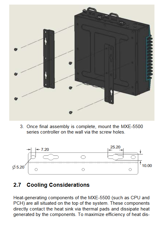
Remove the bottom rubber pad and use the matching bracket to fix the body. When installing, the heat dissipation fins should face upwards, and a ventilation space of ≥ 5cm should be reserved at the top to ensure heat dissipation efficiency.
Hard requirements for heat dissipation
The heat source of the whole machine is concentrated on the top fins, and it is forbidden to wrap or cover the heat dissipation surface in a closed manner. The ventilation gap between the upper and lower parts must be ensured in high temperature environments.
Driver installation instructions
Download the driver from Linghua’s official website and install the chipset, graphics card, and four-way network card in sequence USB3.0、 Audio, SEMA management tool, WDT&DIO development library.
Appendix A: Watchdog WDT and Isolation DIO Windows Development Library
A1 Watchdog API (C/C++)
Core functions: InitWDT initialization, SetWDT timeout setting (in seconds/minutes), StartWDT start, ResetWDT feed dog, StopWDT close; When the program freezes and the dog is not fed, the hardware automatically restarts the entire machine, accompanied by a complete demo source code.
A2 Isolation DIO Digital API
Core functions: GPIO-INnit initializes resources, GPI-Read reads 8 DI levels, GPOWrites outputs DO high and low levels, GPOReads reads the current output status; Support batch control of IO channels through bit operations, suitable for the development of production line sensors and relay control programs.
Appendix B: Complete AMI Aptio BIOS Setup Manual
Press Del to enter BIOS during startup, press F7 to quickly start menu, support administrator/user two-level passwords, five main menus:
B1 Main (Basic Information Page)
Display CPU, memory, BIOS version, system time, hardware factory information, only basic viewing and time modification.
B2 Advanced (industrial control core configuration, divided into 13 sub menus)
CPU configuration: Hyper threading, VT virtualization, AES encryption, CPU energy-saving C-State, overheat protection offset threshold;
Memory configuration: DDR4 frequency, dual channel information viewing;
System proxy SA: VT-d direct access, graphics card reserved video memory (DVMT);
Onboard devices: 6-way serial port mode switching (RS232/422/485), four-way network card PCIe boot switch, HD audio, SATA/CFast/M2 storage switch;
Power management: power-off recovery strategy (power on/off/last state), RTC timed power on, remote wake-up of network card;
USB global configuration: Legacy DOS compatibility, XHCI takeover, USB boot switch;
SATA mode: AHCI/compatibility mode switching;
CSM compatibility: Traditional BIOS/UEFI boot switch, compatible with older operating systems;
AMT remote management, TPM 1.2 security chip switch;
Network stack UEFI PCIe, system hardware health panel (real-time temperature and voltage, power on statistics), boot watchdog.
B3 Security Menu
Administrator/user graded boot password, RTC and BIOS read-write lock to prevent parameter tampering.
B4 Boot startup menu
Customize USB/solid-state/CFast/network boot priority, fast boot, NumLock boot status, full screen OEM LOG switch.
B5 Save&Exit Exit menu
Save modifications, restart, discard modifications, load stable fault default, load performance optimal default, start EFI Shell.
BIOS troubleshooting
When the password is forgotten or there is an abnormal startup, power off and short-circuit the motherboard to clear the CMOS jumper 2-3 pins, restoring all factory parameters.
Appendix C: SEMA 3.0 Visual Operations Tool
Windows graphical management software, eight major function pagination, core tool for remote monitoring and debugging of the entire machine:
Overview page: displays the motherboard serial number, BIOS/BMC firmware, and supported feature list (watchdog, temperature control, logs);
System Health Page: Real time CPU/board temperature, fan speed, overall power consumption, cumulative running time, power on times, last restart reason; Support data mean filtering;
User flash memory: 1KB onboard flash memory, supports hexadecimal/string read and write, stores device custom parameters;
Hardware control page: watchdog duration setting, LVDS backlight brightness adjustment, intelligent temperature control fan curve (four temperature regulation thresholds);
Hardware monitor: real-time temperature/power consumption/voltage curve chart, supports log file export (table format can be imported into Excel);
I2C bus: 4-channel external I2C read-write, supports 100/400kHz rate, compatible with external sensors;
GPIO control: batch set IO input/output direction, read/write level, bit logic operation;
Status bar: Prompt whether to restore BIOS startup due to malfunction.
SEMA Overview Interface
SEMA System Health Interface
SEMA hardware control interface
Safety operation standards
Power off during the entire disassembly and assembly process, and prohibit liquids, dust, and oil from entering the chassis;
2. The DC voltage is strictly between 9~32V, and reverse connection/overvoltage can directly damage the power supply circuit of the motherboard;
The top heat dissipation fins are at high temperature, and it is forbidden to touch them with bare hands during operation to avoid burns;
Only 4 authorized Linghua engineers dismantle and repair the jumper, and privately dismantle or modify the jumper loses the original factory warranty;
5 lithium battery models must be matched, and discarded batteries should be treated as hazardous waste.