ADLINK IMB-M43H Industrial ATX Motherboard
Product Introduction and Packing Selection
1.1 Standard packing list
1 IMB-M43H motherboard, rear I/O board
1.2 Optional Accessories
2-port USB blocking cable, single LPT printing blocking cable, 2-channel serial port blocking cable, LGA1151 2U heat dissipation module
Complete Hardware Core Specifications
2.1 Core Computing Platform
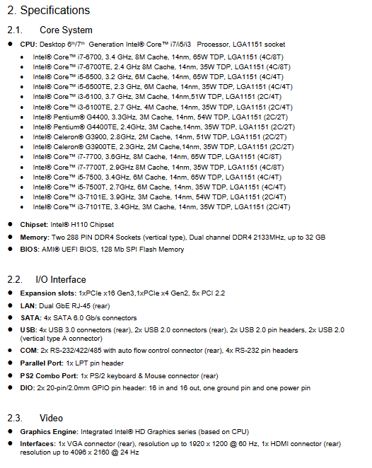
CPU: LGA1151 slot, 6th/7th generation desktop Core i7/i5/i3, Pentium, Celeron, distinguishing between 35W low-power TE embedded version and 51/54/65W standard version, 14nm process, supporting VT virtualization and hyper threading.
Chipset: Intel H110
Dual 288Pin DDR4 memory slots, dual channel DDR4 2133MHz, maximum 32GB
BIOS 128Mb AMI UEFI SPI firmware, graphical visual settings interface
2.2 Expansion Slot (Core Industrial Advantage)
1 x PCIe 3.0 x16 (single display/high-speed acquisition card), 1 x PCIe 2.0 x4, 5 standard PCIe 2.2 slots, maximizing compatibility with older industrial ISA/PCI acquisition devices.
2.3 Overview of I/O interfaces
Rear panel IO
Network port: Dual Intel Gigabit LAN (I219-LM+I211-AT), supporting PCIe network boot and WOL remote wake-up
Serial port: 2-channel COM5/6, hardware supports RS232/422/485 with automatic flow control
Display: VGA (1920 × 1200)+HDMI( 4K@24Hz )
USB: 4xUSB3.0, 2xUSB2.0
Audio: Mic In/Line In/Line Out three hole
PS/2 composite keyboard mouse mouth
Built in expansion pins on board
Serial port expansion: 4 RS232 channels from COM1 to COM4
USB Expansion: 2 sets of front USB 2.0 pins, 2 vertical A-type USB ports
Storage: 4 x SATA3 6Gb/s high-speed hard drive interface
GPIO: Two sets of 20 pin general-purpose digital IO, totaling 16 inputs and 16 outputs, supporting 5V/12V jumper switching for power supply
LPT parallel port, front HD audio, chassis cover opening detection, CPU/system/chassis fan, standard front panel pins
2.4 Audio and Video
Display: CPU integrated HD core display, VGA+HDMI dual output, PTN3355BS video signal conversion chip
Audio: Realtek ALC892 8-channel high-definition audio codec
2.5 Environment and Certification
Working temperature: 0 ℃~60 ℃; Storage -40 ℃~85 ℃
Humidity: 95% RH at 40 ℃ without condensation
EMC certification CE/FCC Class B
Version: Standard ATX 305mm × 244mm
2.6 Supporting Operating Systems
Win7 (only 6th generation CPU), Win8.1/10 64 bit; Linux distributions OpenSUSE, Fedora, Ubuntu 64 bit
2.7 Hardware Function Block Diagram Logic
H110 PCH is connected to 6th/7th generation Core CPUs via DMI bus;
Display branch: Core display output eDP is converted to VGA and native HDMI through PTN3355BS;
High speed peripherals: PCIe split dual gigabit network cards PCIe x16/x4; 4-channel SATA direct connection to PCH;
Low speed peripherals: NCT6106D SuperIO mounted on LPC bus, managing 6 serial ports LPT、 fan PS/2;
Expansion bus: IT8892E+IT8209R bridges 5 traditional PCI slots;
Manage peripherals: ALC892 audio, 32 channel GPIO, SPI BIOS, USB all mounted PCH.
Mechanical Layout and Dimensions
Provide the overall silk screen layout diagram of the motherboard, the distribution diagram of the rear IO panel, and label all connectors, slots, and jumper numbers;
Complete millimeter level mechanical dimension drawings, indicating the length and width of the motherboard, openings, and interface positioning tolerances;
Partition label all hardware locations: CPU socket, DDR4 memory slot, PCIe/PCI expansion slot SATA、 Fan pin GPIO、 Serial port, various functional jumpers (clearing CMOS, AT/ATX switching, serial protocol selection, IO power jumper, etc.).
Complete Definition of Connector Pins and Jumpers
4.1 Rear IO pins
Define HDMI, VGA, USB3.0/2.0, PS/2, 6-channel rear serial port, dual gigabit network port per pin signal, differential data cable, power supply, DDC display communication one by one.
Network port dual color light rule: if the speed light is off=10M, green=100M, orange=1G; if the link light is always on and there is a connection, flashing represents data transmission.
4.2 All built-in onboard pins and pins
Includes SATA, front USB, COM1-4, LPT parallel port, front audio, chassis cover opening detection, three-way fan (CPU/SYS/CHA 4Pin PWM speed regulation), front chassis panel (power button, restart, hard disk/power LED), 24Pin main ATX power supply, 8Pin 12V CPU auxiliary, LPC debugging port, SPI BIOS burning port, 32 channel GPIO, SMBus/I2C bus interface.
4.3 Core Function Jumper (Key for Industrial Configuration)
JCMOS1 (clear CMOS): default 1-2 is normal, 2-3 is short circuited to restore BIOS from factory;
JPSON1 (AT/ATX power mode): default 2-3 ATX (key on); 1-2 AT (power on automatic start);
JSETCOM5/JSETCOM6: Two rear serial port protocol switching jumper, optional RS232/422/485; Set terminal resistance and master-slave mode for matching dialing settings;
JPW1 (GPIO power supply): default suspended, optional+5V/+12V;
JPW2/JPW3: Control SMBus and I2C bus power supply respectively (suspended/3.3V/5V).
Driver Installation
All drivers BSP、 The supporting tools can be downloaded from the corresponding product page on Linghua’s official website, supporting Windows and Linux systems. The hardware underlying APIs are used for GPIO and serial port secondary development.
System Bottom Level Resource Allocation
6.1 Memory Address Mapping
Divide BIOS high bit space, APIC interrupt area, ISA compatible holes, system main memory, DOS compatible memory segments.
6.2 IO Port Address
List serial and parallel ports SATA、USB、SMBus、 Interrupt controller, hardware monitoring fixed hexadecimal IO base address.
6.3 IRQ Interrupt Allocation
Distinguish between traditional PIC mode and APIC advanced interrupt allocation tables, and label 6 serial ports, audio GPIO、SATA、 The network card has a fixed interrupt number, and idle IRQs can be allocated to PCI expansion cards.
6.4 PCI Bus Resources
Complete PCI device bus/device/function number, PCI interrupt routing matrix, 5-way PCI slots, dual network cards, PCIe slot interrupt allocation rules;
6.5 SMBus Device Address
The SMBus identification address of two DDR4 memory modules is used for hardware reading of memory SPD information.
UEFI BIOS Complete Setup (Six Main Menu)
Press the shortcut key to enter the graphical AMI UEFI during startup, support mouse operation, menu hierarchy: Main → Advanced → Chipset → Security → Boot → Save&Exit
7.1 Main
Read only BIOS version, CPU/memory information; The system date and time can be modified.
7.2 Advanced (Advanced settings, maximum functionality)
CPU configuration: Hyper threading, VT virtualization, SGX secure extension, C-State multi-level energy-saving, SpeedStep, TXT trusted execution, core quantity limit;
PCH firmware: ME management engine version, switch;
ACPI power supply: S3 sleep video recovery, PCIe remote wake-up, ringing wake-up;
SuperIO serial parallel port: 6-way serial port switch, IO address/IRQ customization, RS485 automatic flow control for COM5/6, parallel port SPP/EPP/ECP mode;
Hardware monitoring&intelligent fan: real-time CPU/motherboard temperature, three-way fan speed, and various voltages; Support temperature control cruise mode, customize fan start stop temperature and speed control curve;
RTC timed boot, serial console redirection, network stack, CSM compatibility module, USB global configuration, NVMe information.
7.3 Chipset (Chipset Settings)
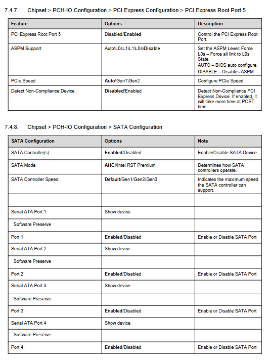
Memory parameters, integrated graphics card DVMT shared video memory, main output device (IGFX core display/PCIe dedicated display);
PCIe link speed, SATA controller AHCI/RST mode, separate switch for all four hard drives;
Dual network card switch, WOL wake-up, power-off and power on recovery strategy, 32 channel GPIO input/output configuration;
HD audio, USB port separately enabled/disabled, I2C serial bus configuration.
7.4 Security
Administrator/user boot password, TXT trusted platform, Secure boot switch.
7.5 Boot (Startup Item)
Startup sequence adjustment, UEFI/Legacy boot mode switching, PXE network boot, fast boot, CSM compatibility switch, NumLock boot status.
7.6 Save & Exit
Save/discard modifications, load factory default, one click restart, EFI Shell startup.
Safety operation standards
Installation and disassembly must disconnect the power supply and perform anti-static operations;
Stay away from liquid and high-temperature sealed environments, ensure ventilation;
There is a risk of explosion due to incorrect replacement of lithium batteries on the motherboard;
The fault can only be repaired by authorized Linghua engineers, and unauthorized disassembly of the power supply and onboard circuits is prohibited;
Remove the power cord from long-term idle equipment.