ADLINK M-322 Industrial ATX Motherboard
Basic Information
Product model: M-322 standard industrial ATX motherboard, material number 50-1Z052-1020, manual version V2.02; Revision records: V2.00 initial version, V2.01 corrected front panel pin diagram, V2.02 corrected text errors and addresses of various offices.
Product positioning: Intel Q35 chipset LGA775 industrial control motherboard, designed for automation, medical, testing and measurement, and telecommunications equipment, catering to both traditional ISA/SATA peripherals and high-speed SATA, dual gigabit, and multi PCI expansion.
Product Overview and Complete Specifications
1.1 Packing standard and optional accessories
Standard packaging: M-322 motherboard, I/O board, 2 SATA data cables, 2 SATA power cables, single serial port board cable, dual serial port board cable, driver CD, this manual.
1.2 Core Hardware Platform
CPU: LGA775 socket, Conroe/Wolfdale/Yonah architecture Core 2 quad core/dual core, Pentium dual core, Celeron, FSB 800/1066/1333MHz, Power consumption of 35-95W;
Chipset: Intel Q35 GMCH+ICH9DO Southbridge; Integrated GMA3100 graphics card, supporting DX9;
Memory 4x240Pin DDR2 DIMM dual channel slot, DDR2 667/800, Maximum 8GB;
BIOS:32Mb AMI SPI BIOS, Equipped with Infineon SLB9635 TPM1.2 hardware security chip;
Storage: 6 SATA 3Gbps (supporting RAID0/1/5/10)+1 PATA IDE+floppy drive interface;
Expansion slots: 1 x PCIe x16 dedicated graphics slot, 1 x PCIe x1, 5-way standard PCI, maximizing compatibility with older data acquisition cards;
Network: Dual Realtek RTL8111C PCIe Gigabit Network, supporting PCIe and WOL remote wake-up;
Serial port system: Rear mounted COM1 (RS232), onboard COM2/3 (RS232), COM4 (RS232/422/485 with jumper switching);
Universal I/O: 12 USB 2.0 channels (rear 4+onboard 8 pins), LPT parallel port, 8 GPIO channels, hardware watchdog, overall voltage/temperature/fan monitoring;
Realtek ALC888 HD 8-channel audio, front audio pin, S/PDIF digital output.
1.3 Electrical power consumption (E6400 dual core no-load/full load test)
The total power consumption during standby and no-load is 31.93W, and during full load 3D pressure testing it is 54.64W;
Power supply rail:+5V,+3.3V,+12V, 5VSB standby power complete parameters.
1.4 Environment and Machinery
Version: Standard ATX 305 × 244mm;
Working temperature: 0-60 ℃, storage: -20~80 ℃; Humidity of 10~90% without condensation;
Certified CE/FCC Class A industrial standards.
1.5 Hardware Architecture Logic
The CPU is connected to the Q35 northbridge via 1333MHz FSB, which controls dual channel DDR2 and GMA3100 core displays PCIe x16;
The North Bridge is connected to the ICH9DO South Bridge via a DMI 2GB/s link;
South Bridge Branch: 6-way SATA, 12 way USB, PCIe bus (dual gigabit network card, PCIe x1), LPC low-speed bus;
LPC mounts Winbond W83627 Super I/O (4-channel serial port, parallel port, floppy drive), TPM, SPI BIOS, ALC888 audio;
The onboard watchdog, hardware monitoring, and GPIO are all connected to the LPC management bus.
Complete Definition of Connectors and Jumpers
2.1 Rear I/O panel interface
PS/2 keyboard mouse DB15 VGA、DB9 COM1、 25 pin LPT parallel port, 4 x USB 2.0, dual RJ45 gigabit network, tri color audio port;
Network port indicator light: orange=link, green=1G, orange=100M, off=10M.
2.2 All onboard built-in pins
Power supply: 24Pin ATX main power supply, 8Pin CPU 12V auxiliary;
Fans: CPU 4Pin PWM fan, chassis fan, power fan;
Storage: SATA1~6, 40Pin PATA IDE, 34Pin floppy drive;
Peripherals: COM2/3/4 serial ports LPT、 8-channel 20 pin GPIO, front audio, CD drive audio, S/PDIF digital audio;
Chassis: Front panel (power button, restart, hard drive/power LED), chassis cover opening detection;
Expansion: 4 sets of USB 2.0 front pins, SPI BIOS burning port, and amplifier audio pins.
2.3 Core Function Jumper (Key Configuration for Industrial Control)
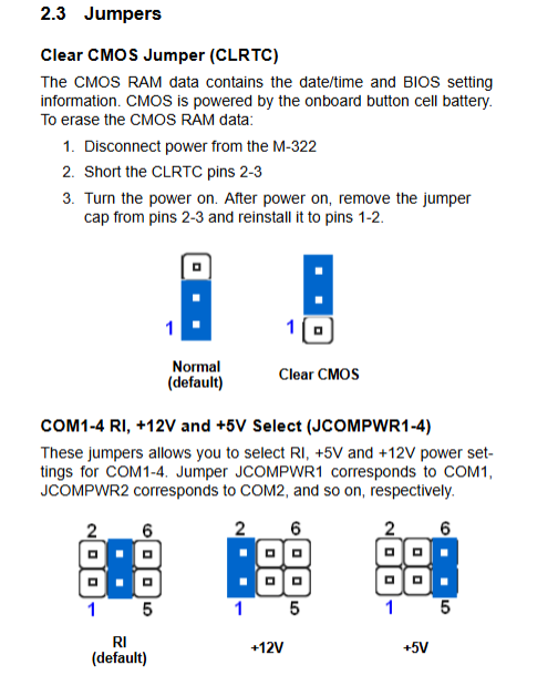
CLRTC: Clear CMOS jumper, power off and short-circuit for 2-3 seconds to restore BIOS from factory;
JCOMPWR1~4: COM1~4 serial port power supply selection, default RI ringing, switchable+5V/+12V;
JCOMPWR5/6/7: COM4 protocol switching, three-level jumper switching RS232/422/485, matching terminal resistor configuration.
Hardware Installation Steps
3.1 LGA775 CPU Installation Specification
Complete power-off and anti-static operation are required;
Open the socket pressure rod and pressure plate, remove the protective cover (to be retained for repair);
Align the CPU triangle with the socket positioning angle and prohibit violent pressing;
Lock the pressure rod with a 4-pack pressure plate and evenly apply thermal grease to install the radiator.
3.2 DDR2 Memory Installation
Dual channel pairing rule: A1/A2 is channel A, B1/B2 is channel B; it is recommended to use memory of the same capacity and specifications; Single/double-sided strips and 128Mb particles have compatibility limitations; 4 1GB memory 32-bit XP cannot recognize the complete 8GB.
3.3 Driver installation process
Driver CD is divided into chipset, graphics card, dual network card, HD audio TPM、 Intel Matrix Storage (RAID) six major directories;
Installing SATA RAID on Windows XP requires F6 floppy disk preloading driver; Vista/Win7 does not require floppy disks; Supports XP/Vista/Win7/Server2008/Fedora12 systems.
AMI BIOS Complete Setup (Enter Del upon Startup)
4.1 Main interface
System time, floppy drive model, 6-way SATA hard drive recognition, SATA mode (compatible/enhanced/RAID/AHCI) configuration.
4.2 Advanced Menu (Core Configuration)
USB configuration: USB switch, Legacy traditional USB support (DOS/PE recognition keyboard and mouse);
Trusted computing: TPM chip enables/clears key;
TXT/Intel VT virtualization switch;
CPU settings: Hyper threading, SpeedStep energy-saving, hardware prefetching, XD antivirus bit;
Chipset settings: memory remapping, shared graphics memory for core displays, main graphics card selection (IGD core display/PCIe dedicated display), spread spectrum clock;
Onboard devices: 4-channel serial port address IRQ, parallel port mode, dual network card PXE boot switch, JMicron PATA controller;
PCI/PnP: BIOS/system allocates PCI interrupts.
4.3 Power menu
ACPS1/S3 standby selection, S3 wake-up video output, hardware monitoring (real-time CPU/motherboard temperature, various voltages, fan speed), intelligent fan three speed curve (mute/balance/performance);
APM configuration: Power on/off recovery, RTC timed power on, programmable watchdog (1-255 seconds/minute).
4.4 Boot Start Menu
Start device priority, quick self-test, startup NumLock status, startup password, error F1 waiting switch.
4.5 Exit Exit menu
Save/discard modifications, load secure/optimal factory defaults.
Two appendices: Industrial Development Data
Appendix A: Watchdog Timer WDT
Function: Automatically reset the entire machine after 1-255 seconds/minute timeout, BIOS can record watchdog restart flag;
Provide sample code for reading and writing low-level IO ports (W83627 Super I/O register operation) for secondary development on Windows/Linux.
Appendix B: System Bottom Layer Resources
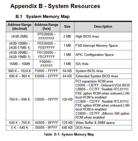
Complete table: memory address mapping, DMA channels, fixed/variable IO ports, PIC/APIC dual-mode IRQ interrupt allocation, PCI device bus mapping, PCI interrupt routing matrix, used for troubleshooting interrupt conflicts in industrial control cards and developing underlying drivers.
Safety operation standards
Disassembly and assembly must be powered off to prevent static electricity. Incorrect replacement of lithium batteries on the motherboard poses a risk of explosion;
2. Prohibit the use of liquids, dust, and high-temperature sealed environments;
3. Power supply and motherboard faults can only be repaired by authorized Linghua engineers, and unauthorized disassembly is prohibited;
4. Long term idle equipment disconnected from mains power.